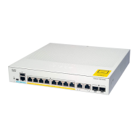
(Optional) DIN rail mount
(only with Cisco Catalyst 1000 16-port
switch models)
10Four rubber mounting feet (51-0089)3
Power Adaptor - PWR-ADPT-18W
1
11Compliance documentation
(78-101287-01)
4
Power Adaptor - PWR-ADPT-85W
2
12Three number-8 screws (48-1689-01)5
Power Adaptor - PWR-ADPT-150W
3
13Screw template (47-100996-02)6
(Optional) Console cable or USB cable7
1
for C1000-8T-E-2G-L and C1000-16T-E-2G-L switch models
2
for C1000-8P-E-2G-L switch models
3
for C1000-8FP-E-2G-L and C1000-16P-E-2G-L switch models
Tools and Equipment
Obtain these necessary tools:
• A Number-2 Phillips screwdriver.
• Drill with #27 drill bit (0.144-inch [3.7 mm]) for mounting an 8-port and 16-port switch.
Installation Guidelines
When determining where to install the switch, verify that these guidelines are met:
• Clearance to the switch's front and rear panel should meet these conditions:
• Front-panel LEDs can be easily read.
• Access to ports is sufficient for unrestricted cabling.
• AC power cord can reach from the AC power outlet to the connector on the switch's rear panel.
• Cabling is away from sources of electrical noise, such as radios, power lines, and fluorescent lighting
fixtures. Make sure that the cabling is safely away from other devices that might damage the cables.
• Airflow around the switch and through the vents is unrestricted. To avoid any flow blockage, we strongly
recommend these guidelines:
• Allow at least 3 in. (7.6 cm) of clearance from the left and the right sides, and the front and rear of
the switch.
• Allow at least 1.75 in. (4 cm) of clearance from the top cover, if you are installing the switch in
upright position.
• Allow at least 3 in. (7.6 cm) of clearance from the top cover, if you are installing the switch.
Cisco Catalyst 1000 Series 8-Port and 16-Port Switch Hardware Installation Guide
18
Switch Installation
Tools and Equipment
 Loading...


