Procedure
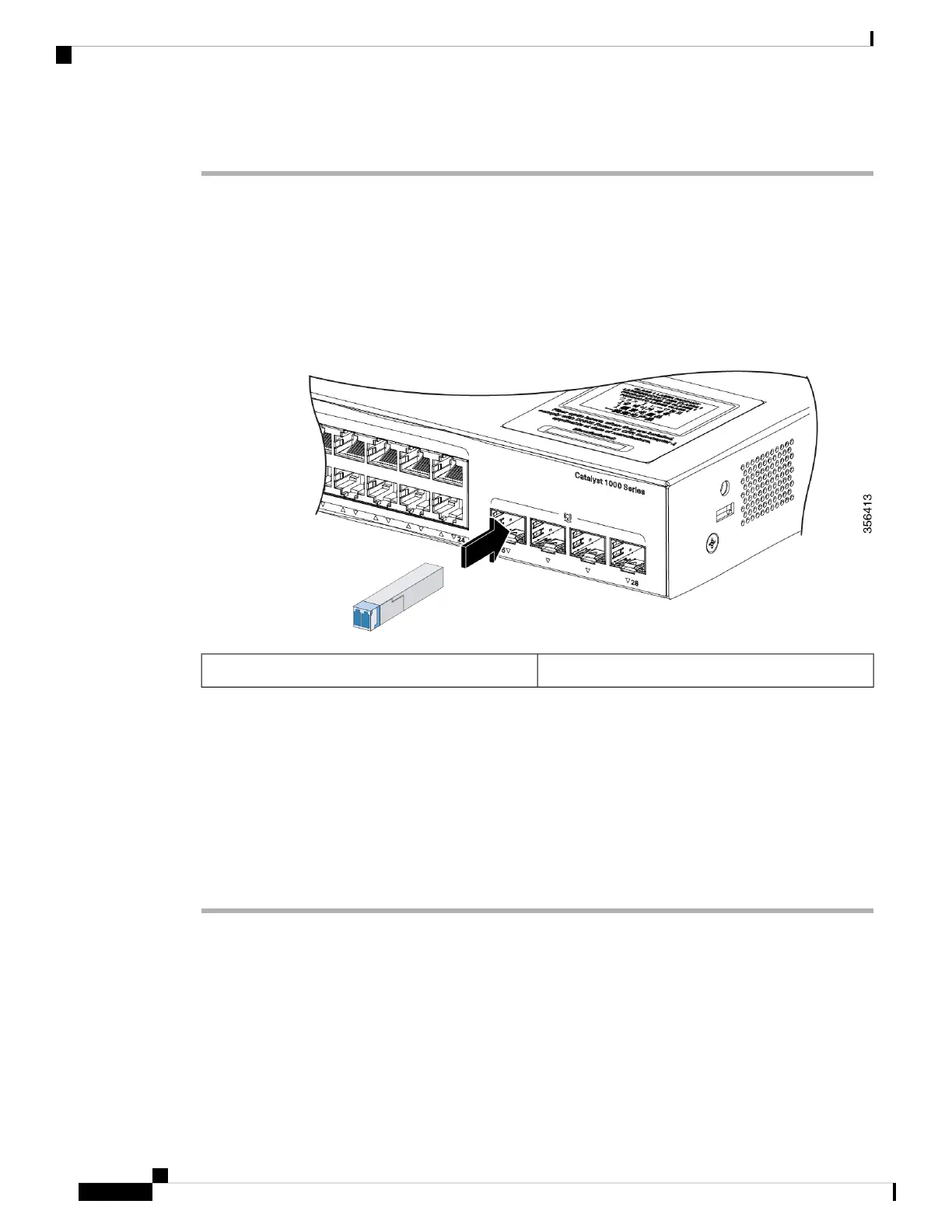
Step 1 Connect one end of the cable to the SFP module port. Insert a four twisted-pair, straight-through cable when
you connect to servers, workstations, and routers. Insert a four twisted-pair, crossover cable when you connect
to switches or repeaters.
Step 2 Connect the other end of the cable to an RJ-45 connector on the other device.
Figure 21: Connecting to a 1000BASE-T SFP Module
RJ-45 connector1
Step 3 Observe the port status LED.
• The LED turns green when the switch and the other device have an established link.
• The LED turns amber while the STP discovers the network topology and searches for loops. This process
takes about 30 seconds, and then the port LED turns green.
• If the LED is off, the other device might not be turned on, there might be a cable problem, or there might
be a problem with the adapter in the other device.
Step 4 If necessary, reconfigure and restart the switch or other device.
10/100/1000 PoE+ Port Connections
A powered device connected to a PoE port does not receive power:
• Use the show hardware led port power privileged EXEC command to show the PoE status for all ports.
• Use the show interfaces privileged EXEC command to see if the port is in error-disabled, disabled, or
shutdown. Reenable the port if necessary.
Cisco Catalyst 1000 Series 24-Port and 48-Port Switch Hardware Installation Guide
32
Switch Installation
10/100/1000 PoE+ Port Connections
 Loading...