B-1
Catalyst 2900 Series XL Modules Hardware Installation Guide
78-5912-03
APPENDIX
B
Connectors and Cables
This appendix describes the cables and connectors for the Catalyst 2900 series
modules.
10/100 Module Cabling
The 10/100 module ports are marked with an X, indicating that they have their
transmit (TD) and receive (RD) signals internally crossed for attachment of an
Ethernet adapter using a straight-through cable.
When connecting the 10/100 ports to 10BaseT or 100BaseTX servers and
workstations, ensure that you use a Category 5 straight-through cable. When
connecting to other switches or repeaters, ensure that you use a c rossover cable.
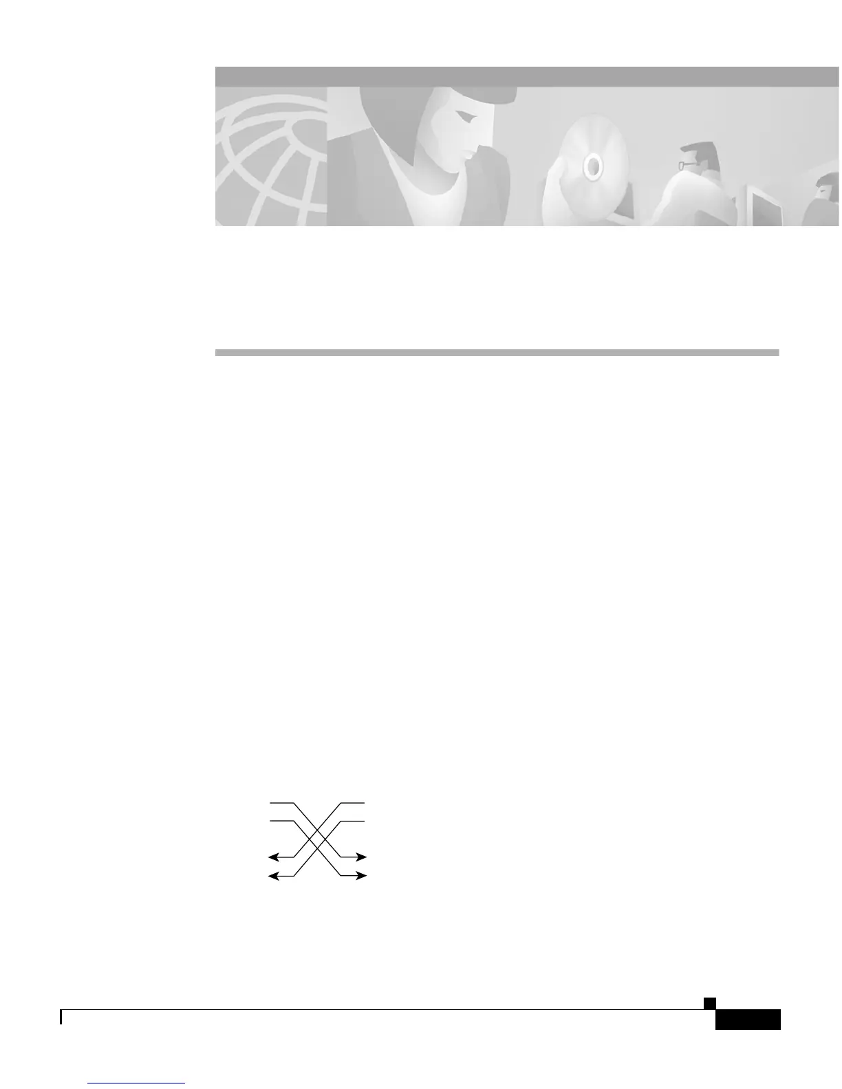
The schematics of crossover and straight-through cables are shown in Figure B-1.
Figure B-1 Crossover and Straight-Through Cable Schematics
Switch
3 TD+
6 TD–
1 RD+
2 RD–
Switch
3 TD+
6 TD–
1 RD+
2 RD–
H5579
 Loading...