32
Installing and Connecting the Router
Power-Supply Modules
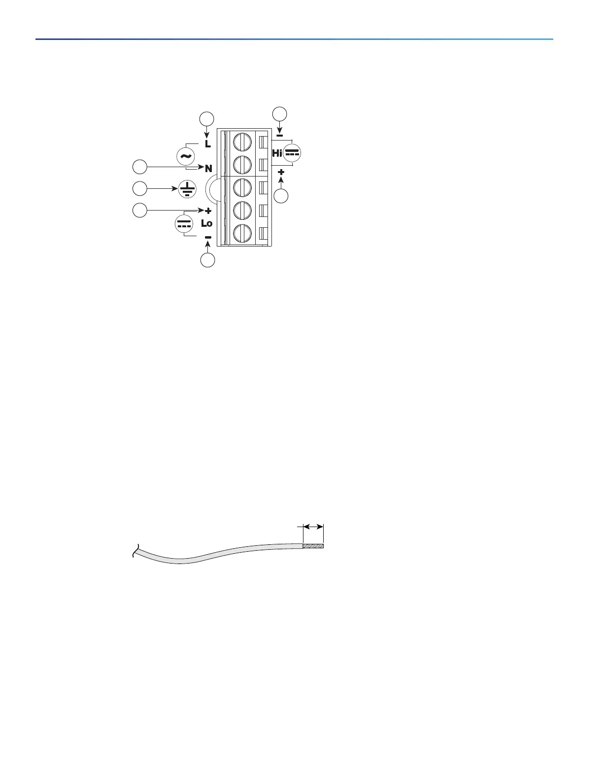
Figure 6 Power-Input Terminal Designations
Note: The power-supply module 1 connection is labeled PSU1, and the power-supply module 2 connection is
labeled PSU2. Ensure that you connect the wires to the correct terminal screws.
3. Use twisted-pair copper wire to connect from the power-input terminal to the power source.
Note: Use 12-AWG (minimum) for the low-voltage DC power supply module. Use 14-AWG (minimum) or 12-AWG
(maximum) for the high-voltage DC or AC power supply module.
4. Strip each of the two wires to 0.25 inch (6.3 mm) ± 0.02 inch (0.5 mm). See Figure 7 on page 32
Figure 7 Stripping the Input Power Source Wire
Note: Do not strip more than 0.27 inch (6.8 mm) of insulation from the wire. Stripping more than the recommended
amount of wire can leave exposed wire from the connector after installation.
5. To connect AC power:
Warning: When installing or replacing the unit, the ground connection must always be made first and
disconnected last. Statement 1046
a. Connect the Ground wire (the green or green/yellow lead of the cable) into the terminal marked with the ground
symbol. See item 7 in Figure 6 on page 32
b. Connect the Line wire (the black or brown lead of the cable) into the terminal screw labeled L.
See item 1 in Figure 9 on page 34.
1 Line connection for AC power
1
4 Positive connection for high-voltage DC
2 Neutral connection for AC power 5 Negative connection for low-voltage DC
3 Negative connection for high-voltage DC 6 Positive connection for low-voltage DC
7 Ground connection
1
Note that the line connection for AC power and the negative connection for high-voltage DC power
share the same power input terminal—that is, this terminal can be used for either AC or DC power. The
same is true for the terminal for the neutral connection for AC power and the positive connection for
high-voltage DC power—the same terminal can be used for either AC or DC power.
0.25 in. (6.3 mm)
±
0.02 in. (0.5 mm)
60531

 Loading...

