33
Installing and Connecting the Router
Power-Supply Modules
c. Connect the Neutral wire (the white or blue lead of the cable) into the terminal screw labeled N.
See item 2 in Figure 9 on page 34.
Note: Ensure that you cannot see any wire lead. Only wire with insulation should extend from the terminal screw.
d. Use a tie wrap to secure the cable to the central strain relief tab next to the terminal block on the chassis. Secure
the cable immediately adjacent to the terminal block to minimize strain on the cable.
The strain relief mechanism consists of three metal loops built into the chassis next to the terminal block. See
Figure 8 on page 33.
Note: Do not overtighten the tie wrap to the loops. This could damage the wiring insulation. An overtightened tie
wrap could cause cold-flow of the wire insulation, which in turn could cause shorting of the power source to the
chassis.
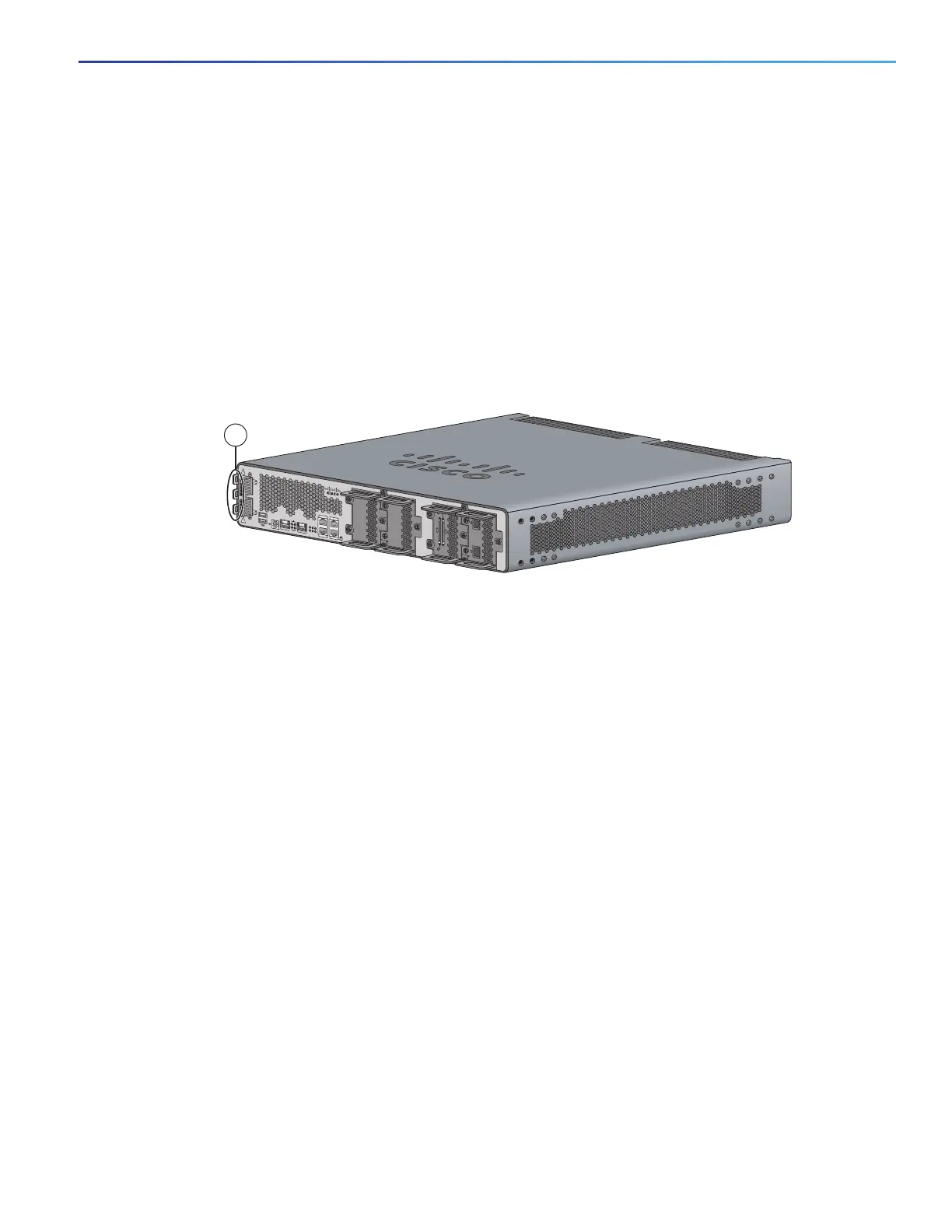
Figure 8 Using Tie Wraps with the Strain Relief Mechanism
Caution: Ensure that all strands of a stranded wire are properly captured into the terminal block. A loose strand
could possibly short the chassis and result in a hazard.
e. Use minimum 14 AWG or maximum 12 AWG copper wire to connect the router to a 15 A branch circuit in
accordance with local electrical code requirements.
6. Fully insert the un-insulated lead in to the terminal block and screw each captive screw on the terminal block tight
to ensure proper connection.
Caution: The AWG size of the wires feeding power to the input terminal block is a minimum of 14 AWG (2.0 mm2)
or a maximum of 12 AWG (3.309 mm2), all for a 15 Amp branch circuit. 12 AWG is the largest wire that the
terminal block will accept.
7. Torque the captive screws (above the wires) to 8.5 in-lb (± 0.5 in-lb).
Caution: Do not touch the terminal block when energy is restored. The terminal block screw heads and any
exposed wiring could have hazardous line voltages (depending on the voltage source). The Cisco CGR 2010
router is intended to be installed in a restricted access location and serviced by trained personnel only.
8. Connect the other end of the line wire (the wire connected to L) to the line terminal on the AC power source.
9. Connect the other end of the neutral wire (the wire connected to N) to the neutral terminal on the AC power source.
10. Turn on the power at the AC circuit, then verify that the following LEDs are green:
— On the power-supply module: PSU OK LED. See Figure 6 on page 12
— On the router: PSU1 (bottom) or PSU2 LED (top). See Figure 6 on page 12
1 Tie wraps to the central strain relief tab.
199587
SFP 0/0
SFP 0/1
GE 0/0
GE 0/1
CONSOLE
AUX
EN
EN
Cisco CGR 2010
PSU2PSU1
L
N
N
L
+
Lo
-
-
Lo
+
-
HI
+
+
HI
-
0
1
EN
SPD
CF
1
PS
2
ACT
SYS 0
1
SL
SL
SLOT 3 SLOT 2
SLOT 1 SLOT 0
CONN CONN
0-3
4-7
CD/LP AL CD/LP AL
P1 P0
1

 Loading...

