E-8
Cisco Physical Security Multiservices Platform Series User Guide
OL-21838-03
Appendix E 16 x D1 and 8 x D1 Video Capture Cards
Understanding Video Channel Numbers
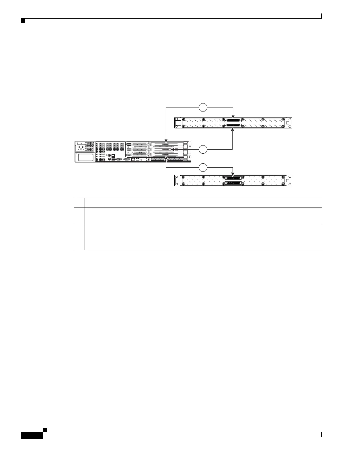
2-RU Multi Services Platform Series Device Channel Numbers
In a 2-RU Multiservices Platform Series, there are three slots for 16 and 8 port video capture cards.
Figure E-5 shows the location of the video cards, and the corresponding connections to the BNC
breakout panels.
Figure E-5 2-RU Multi Services Platform Series Device Video Capture Card Port Numbers
1 Top video capture card connection for ports 1 through 16. Use the top connector of a BNC panel.
2 Middle video capture card connection for ports 17 through 32. Use the bottom connector of a BNC
panel.
3 Bottom video capture card connection for ports 33 through 48. Use the top or bottom connector of
a second BNC panel.
Note This card supports ports 33 through 48 regardless of the labels on the BNC panel.
 Loading...