3-6
Cisco IR829 Integrated Services Router Hardware Installation Guide
Chapter 3 Connecting the Router
Verifying Connections
Verifying Connections
To verify that all devices are properly connected to the router, first turn on all the connected devices,
then check the LEDs. To verify router operation, refer to
Table 3-1.
For full LED description, see Chapter 1, “LEDs”
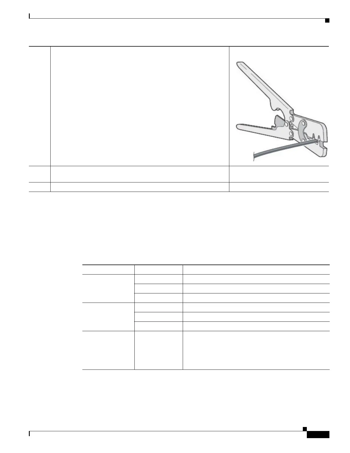
Step 3
Using the pins included in the kit, crimp each pin onto a wire.
Step 4
Insert the pins into the power connector, referring to previous figures for
guidance.
Step 5
Plug the connector into the power entry receptacle.
Ta b l e 3-1 Verifying the Router Operation
Power and Link LEDs to Check Normal Patterns
PWR Green steady On Normal operation
Green (blinking) Boot up phase or in ROM Monitor mode
Yellow System shutdown due to under or over voltage conditions
GE0 WAN Steady On Link is up
Flashing Transmitting and Receiving data
Off No network activity.
Ethernet LAN
Switch Ports
Single LED per
port
Off — No link
Green Steady on — Link is up
Green Blink — Transmitting and Receiving data
Yellow — POE Fault, implies no link
 Loading...