2-4
Cisco PIX Firewall Hardware Installation Guide
78-15170-01
Chapter 2 PIX 501
Connecting a Power Supply Module to the PIX 501
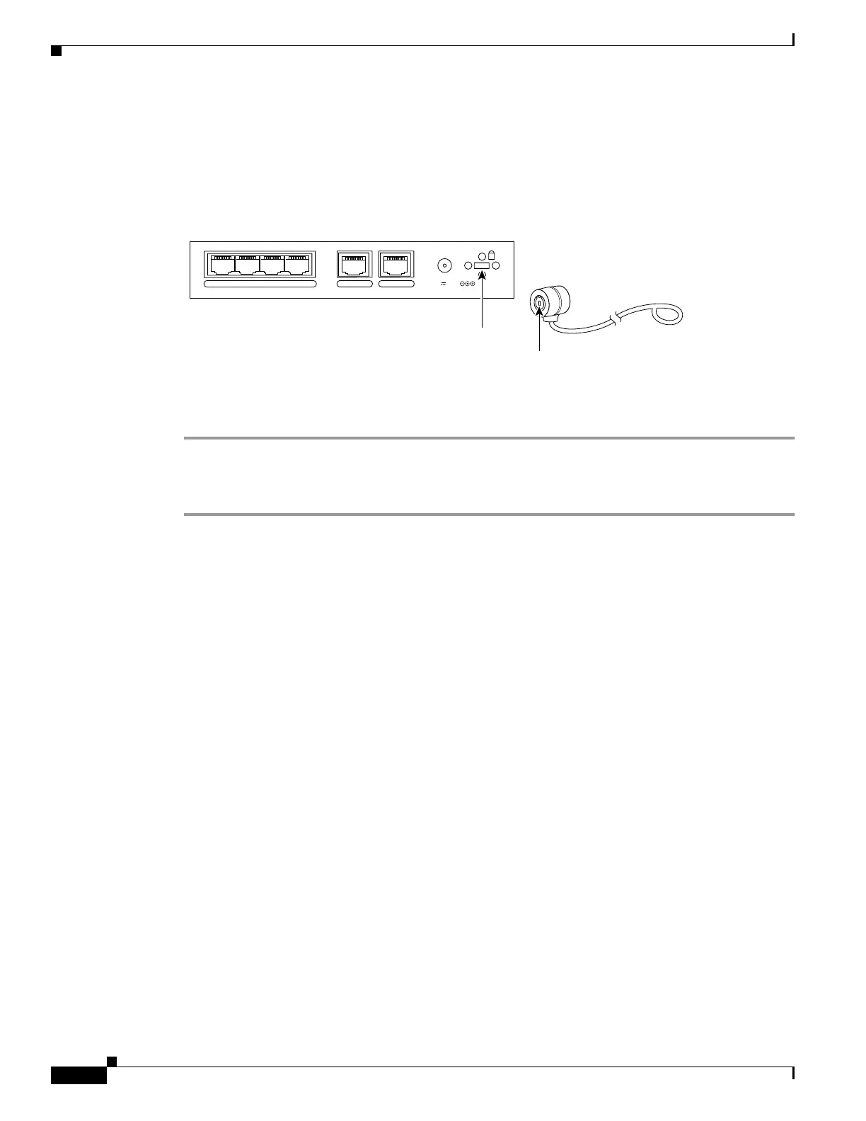
PIX 501 Cable Lock
The PIX 501 includes a slot that accepts standard desktop cable locks to provide physical security for
small portable equipment, such as laptop computers. (See Figure 2-5.)
Figure 2-5 PIX 501 Security Cable Lock
Complete these steps to install a security cable lock:
Step 1 Attach the cable lock to the lock slot on the back panel of the PIX 501.
Step 2 Follow the directions from the manufacturer for attaching the other end of the device for securing the
PIX 501.
POWER
43
2
1
0 CONSOLE
3.3V 4.5A
61929
Lock slot
Cable lock
(not included)
 Loading...


