5-15
Cisco PIX Firewall Hardware Installation Guide
78-15170-01
Chapter 5 PIX 520
Installing a Circuit Board in the PIX 520
Installing a Circuit Board in the PIX 520
The information in this section refers to the installation of a circuit board in the PIX 520. This section
includes the following topics:
• PIX Firewall 16 MB Flash Circuit Board, page 5-18
• PIX Firewall VPN Accelerator Circuit Board, page 5-19
• Gigabit Ethernet Circuit Board, page 5-20
• Installing the PIX 520 DC Model, page 5-21
Complete these steps to install a circuit board in the PIX 520:
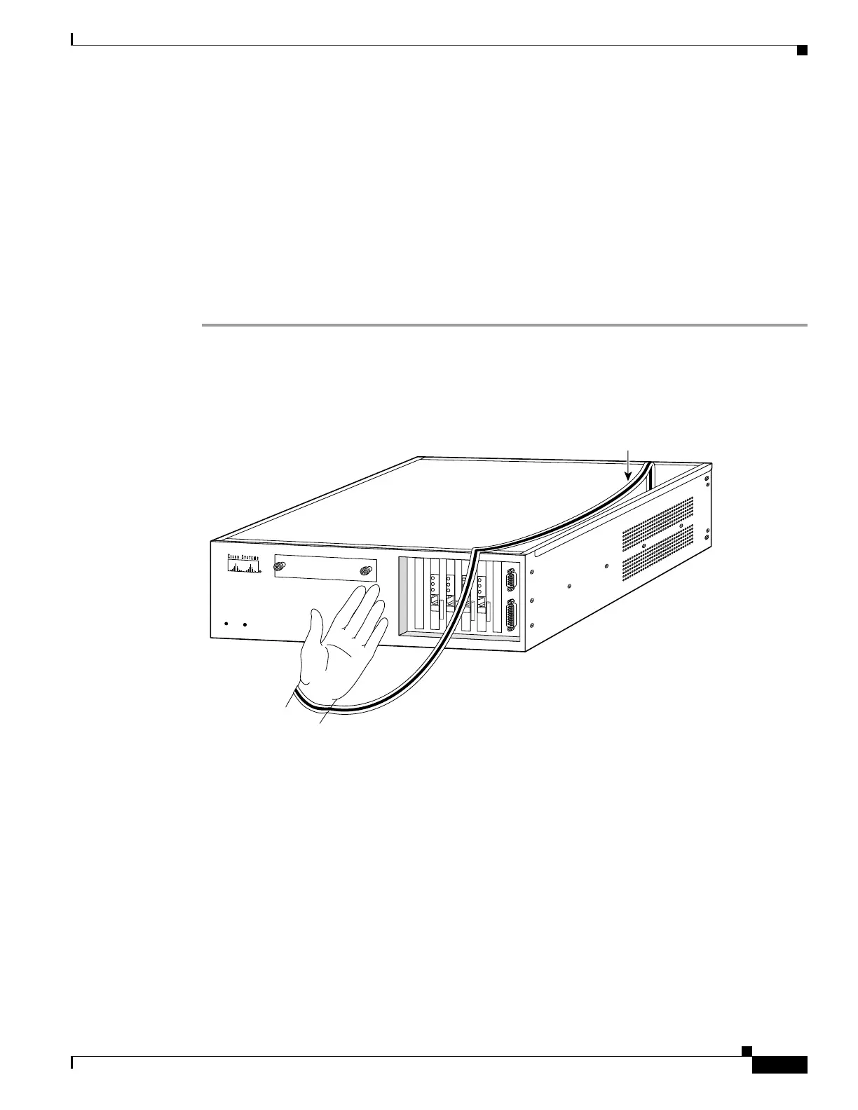
Step 1 Locate the grounding strap from the accessory kit. Fasten the grounding strap to your wrist so that it
contacts your bare skin. Attach the other end to bare metal inside the PIX Firewall chassis as shown in
Figure 5-17.
Figure 5-17 Attaching Grounding Strap to Your Wrist and to the PIX Firewall
Step 2 Insert the new circuit board, as shown in Figure 5-18, and secure it using the screw provided with the
circuit board.
18352
PIX
Firewall
S
E
R
IE
S
RESET
PO
W
ER
DATA
LNK
E
T
H
E
R
N
E
T
0
ACT
100
TX
DATA
LNK
E
T
H
E
R
N
E
T
0
ACT
100
TX
DATA
LNK
E
T
H
E
R
N
E
T
0
ACT
100
TX
DATA
LNK
E
T
H
E
R
N
E
T
0
ACT
100
TX
Copper foil
 Loading...


