6-19
Cisco PIX Firewall Hardware Installation Guide
78-15170-01
Chapter 6 PIX 525
Installing a DC Power Supply
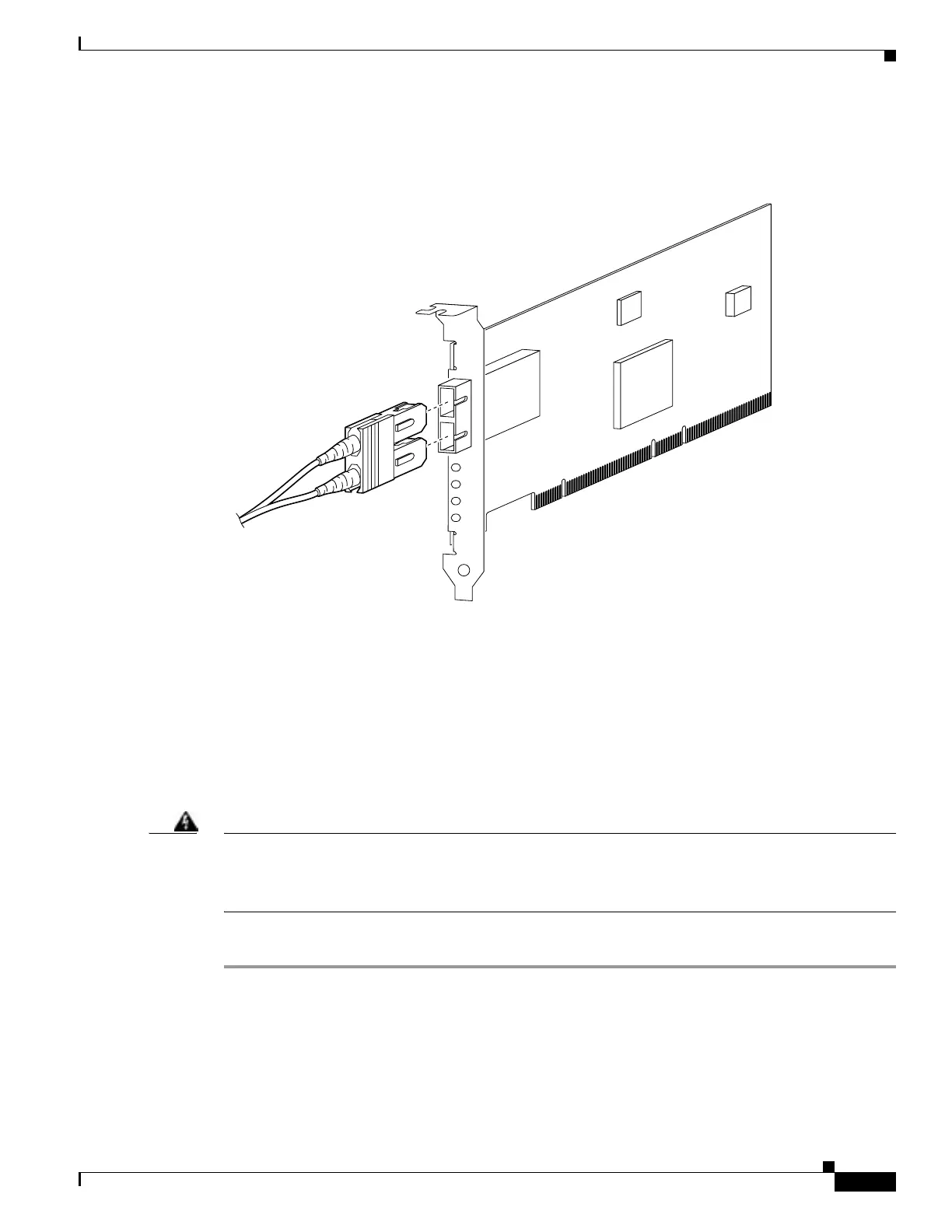
The Gigabit Ethernet circuit board and the fiber optic cable connection are shown in Figure 6-19.
Figure 6-19 Gigabit Ethernet Circuit Board
The Gigabit Ethernet circuit board has three LEDs:
• TX—Transmitting data
• RX—Receiving data
• LINK—The Gigabit Ethernet circuit board has established a network connection
Installing a DC Power Supply
Warning
Before performing any of the following procedures, ensure that power is removed from the DC circuit.
To ensure that all power is OFF, locate the circuit breaker on the panel board that services the DC
circuit, switch the circuit breaker to the OFF position, and tape the switch handle of the circuit
breaker in the OFF position.
Complete these steps to install the DC power supply:
Step 1 Place the power supply as shown in Figure 6-20, and then slide it toward the rear panel. You will be able
to feel the chassis hook engage with the slot on the bottom of the power supply.
Step 2 Reinstall the three screws that secure the power supply on the back panel of the chassis.
33010
T
X
R
X
LIN
K
 Loading...


