Step 2 Insert the stripped end of the grounding cable into the open end of the grounding lug.
Step 3 Use the crimping tool to secure the grounding cable in the grounding lug.
Step 4 Remove the adhesive label from the grounding pad on the fabric interconnect.
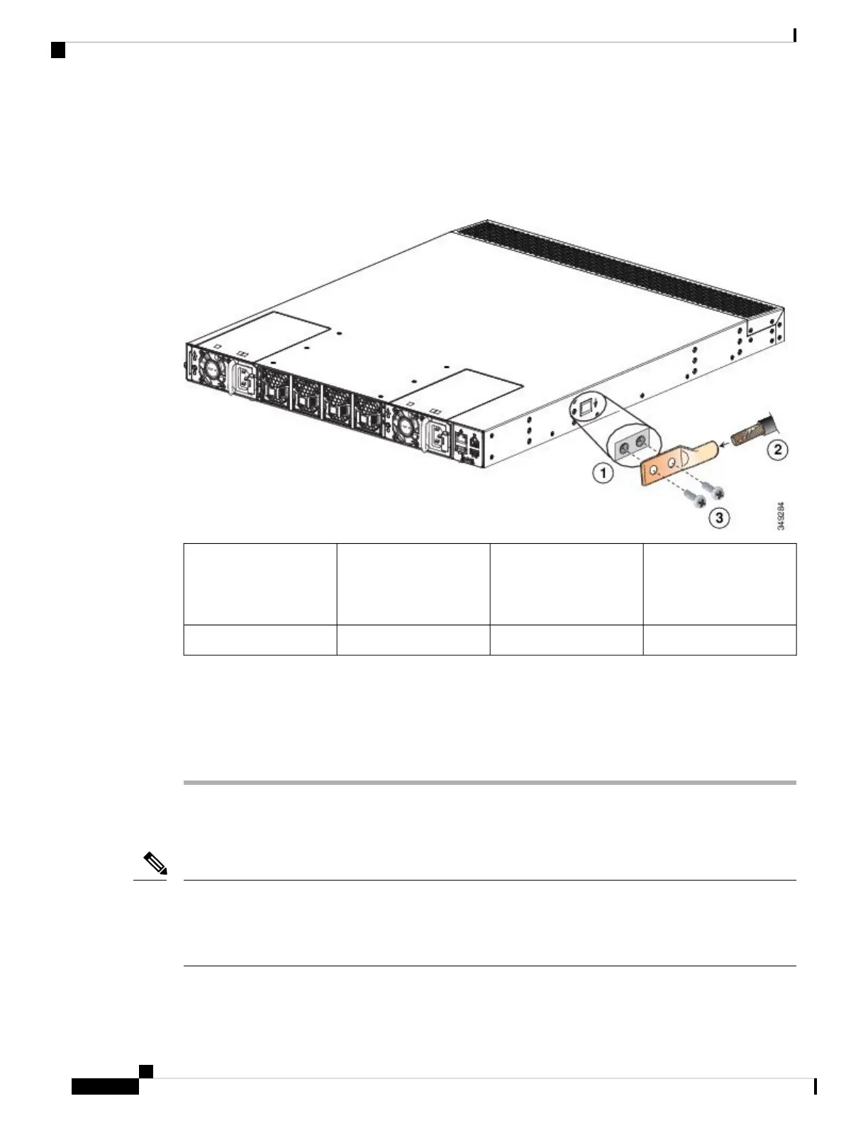
Figure 13: Connecting the System Ground (Cisco UCS 6454 FI shown)
Stripped copper wire2Grounding pad on FI,
with two M4-threaded
screw holes (enlarged
view shown)
1
--M4 screws (two)3
Step 5 Place the grounding lug against the grounding pad so that there is solid metal-to-metal contact, and insert the
two M4 screws through the holes in the grounding lug and into the grounding pad.
Step 6 Ensure that the lug and cable do not interfere with other equipment.
Step 7 Prepare the other end of the grounding cable and connect it to an appropriate grounding point in your site to
ensure adequate earth ground.
Starting the System
Do not connect the Ethernet port to the LAN until the initial system configuration has been performed. For
instructions on configuring the system, see the Configuration Guide for the version of Cisco UCS Manager
that you are using. The configuration guides are available at this URL: http://www.cisco.com/c/en/us/support/
servers-unified-computing/ucs-manager/products-installation-and-configuration-guides-list.html
Note
Cisco UCS 6400 Series Fabric Interconnect Hardware Installation Guide
24
Installing the Cisco UCS Fabric Interconnect
Starting the System

 Loading...