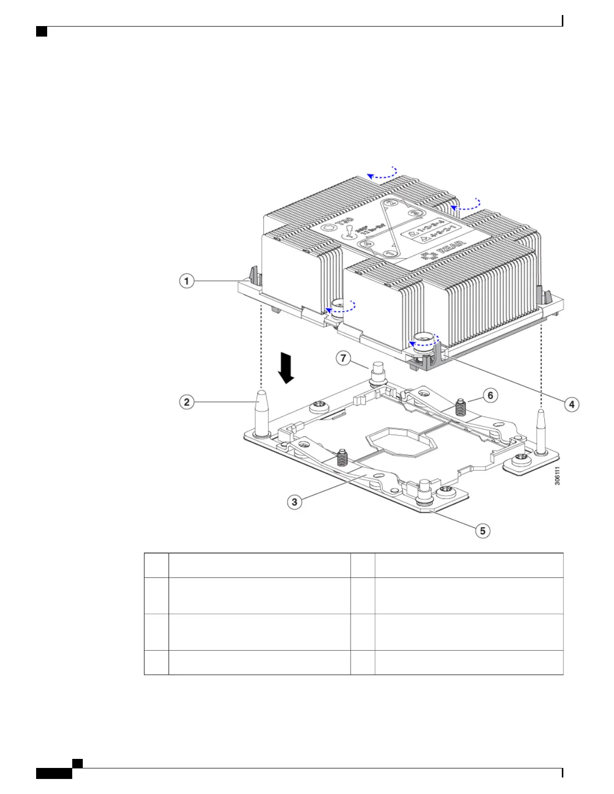
Note the alignment features. The pin 1 angled corner on the heatsink must align with the pin 1 angled
corner on the CPU socket. The CPU socket alignment pins must properly align with the slots on the CPU
carrier and heatsink. Take note of the two different sizes of the alignment pins.
Figure 14: Installing the Heatsink/CPU Assembly to the CPU Socket
CPU socket alignment post (two)2Guide hole in assembly (two)1
Angled corner on heatsink (pin 1 alignment
feature)
4CPU socket leaf spring3
CPU socket leaf spring threaded standoffs6Angled corner on socket (pin 1 alignment
feature)
5
-CPU socket alignment threaded standoffs7
Cisco UCS B200 M5 Blade Server Installation and Service Note
34
Servicing a Blade Server
Replacing a CPU and Heatsink
 Loading...