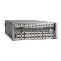
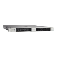
Replacing Components Inside the Main Chassis
Blank faceplates and cover panels serve three important functions: they prevent exposure to hazardous
voltages and currents inside the chassis; they contain electromagnetic interference (EMI) that might
disrupt other equipment; and they direct the flow of cooling air through the chassis. Do not operate
the system unless all cards, faceplates, front covers, and rear covers are in place.
Statement 1029
Warning
When handling server components, handle them only by carrier edges and use an electrostatic discharge (ESD)
wrist-strap or other grounding device to avoid damage.
Caution
You can press the unit identification button on the front panel or rear panel to turn on a flashing, blue unit
identification LED on both the front and rear panels of the server. This button allows you to locate the specific
server that you are servicing when you go to the opposite side of the rack. You can also activate these LEDs
remotely by using the Cisco IMC interface.
Tip
This section describes how to install and replace main chassis components. See also:
• Replacing Components Inside a CPU Module, on page 67
• Replacing Components Inside an I/O Module, on page 90
Replacing a CPU Module
CPU Module Population Rules:
• The server can operate with one or two CPU modules.
• If you have only one CPU module, populate lower bay 1 first.
• If no CPU module is present in upper bay 2, you must insert a blank filler module or the system will not
boot.
• The following restrictions apply when using only a two-CPU configuration (CPU module 2 is not present):
• The maximum number of DIMMs is 24 (only CPU 1 and CPU 2 memory channels).
• Some PCIe slots are unavailable when CPU module 2 is not present:
PCIe Slots Controlled by CPU Module
2
(CPUs 3 and 4)
PCIe Slots Controlled by CPU Module
1
(CPUs 1 and 2)
3, 4, 6, 7, 11, 121, 2, 5, 8, 9, 10
Maintaining the Server
17
Maintaining the Server
Replacing Components Inside the Main Chassis
 Loading...