Supplement Manual
818-1
l-.
.'7
p_,
42,
nit
Uti
Cl.
0
OPERATION
N°
MA.
390-0
: (.heck/n fbi' b driiy/ic c ,Pouee/s on the ,tb,cle
Op. MA. 390-0
SI (InUcil S1I (Tfl1 lebiCl(5
1
CHECKINGTIIE HYDRAULIC COMPONENTS
0
u
0
D
0
0
z
c
0
E
0
0.
fr
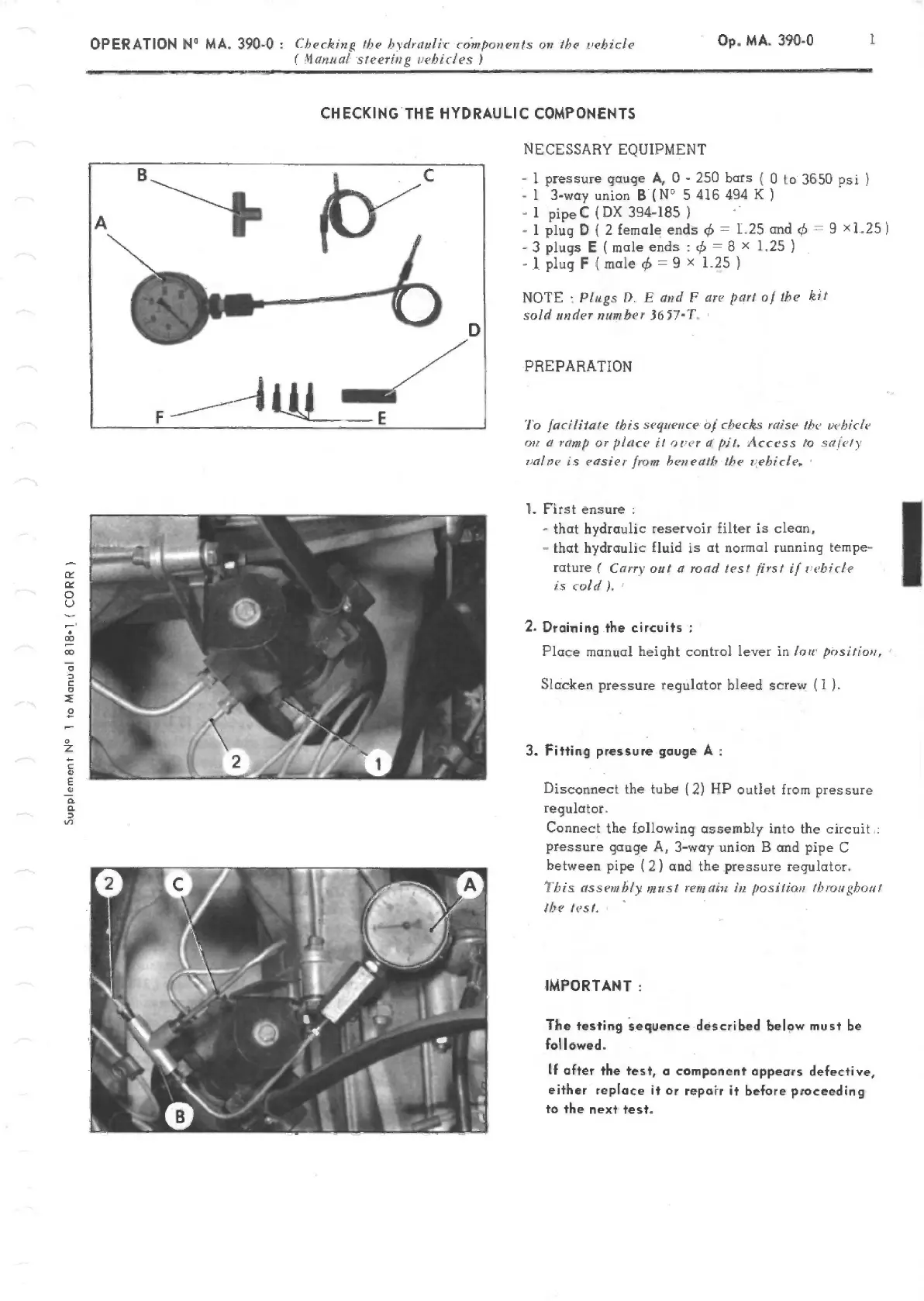
NECESSARY EQUIPMENT
-1 pressure
gauge A, 0-250
bars
(
0 to
3650
pi
-
1 3-way union
B(N0
5416494 K
-
1
pipeC
(DX
394-185
-
1 plug D
{
2
female ends
1.25 and
9 xL25)
-3plugsE(maleends:&=8>
1.25)
-
1 plug
F
(male
9
x
1.25
NOTE
: J'lugs
fl, E and F
are part oj
the
kl!
sold uflder number
36
57'I'.
PREPARATION
'lo facililate this
sequc';lce of checks raise
the iehklc
a ramp
or
place
ii
a
pil.
Access
to
sa/ely
ca/te
is easzer from ben cath tbc
tehicie.
1.
F'irst
ensure
-
that hydraulic reservoir filter is
dean,
-
that
hydraulic
fluid is
at
normal
running
tempe-
rature ( (arr-
out
a
road
test
first
/(
t'ehicfe
is
cold
).
2.
Draining the
circuits
Place manual height
control
lever
in (ou prsitiwi,
Slacken
pressure regulator
bleed
screw
(1
).
3. Fitting pressure gouge
A
Disconnect the tube (2) HP
outlet from pressure
regulator.
Connect
the
following
assembly
into
the
circuit
pressure
gauge A,
3-way union B and pipe
C
between pipe
(2)
and
the pressure regulator.
1 his ass cm
bly mu st
rem alt: in
position
Ibrougbon 1
the
test.
IMPORTANT:
The testing sequene clescribecl below must be
fol
1
owed.
If
after
the
test, a
component
appears
defective,
either
replace it or
repair
it
before proceeding
to
the next test.
PDF compression, OCR, web-optimization with CVISION's PdfCompressor

 Loading...