t70
C7=
t1, ...
.7'
q-«
'-`
C/]
Ö..
R.,
R..
Ini
-----,
z
Supplement to
Manual 818-1 ADD
I('
[/1
5--
i»>
OPERATION
N°
Mk
640-00
: Charac/ristics ai,d s/hciaI Jcatur(s o ih air'
Op. MA.
640-00
.3
(())r/i/iO/i1/(
SVSI(P1/.
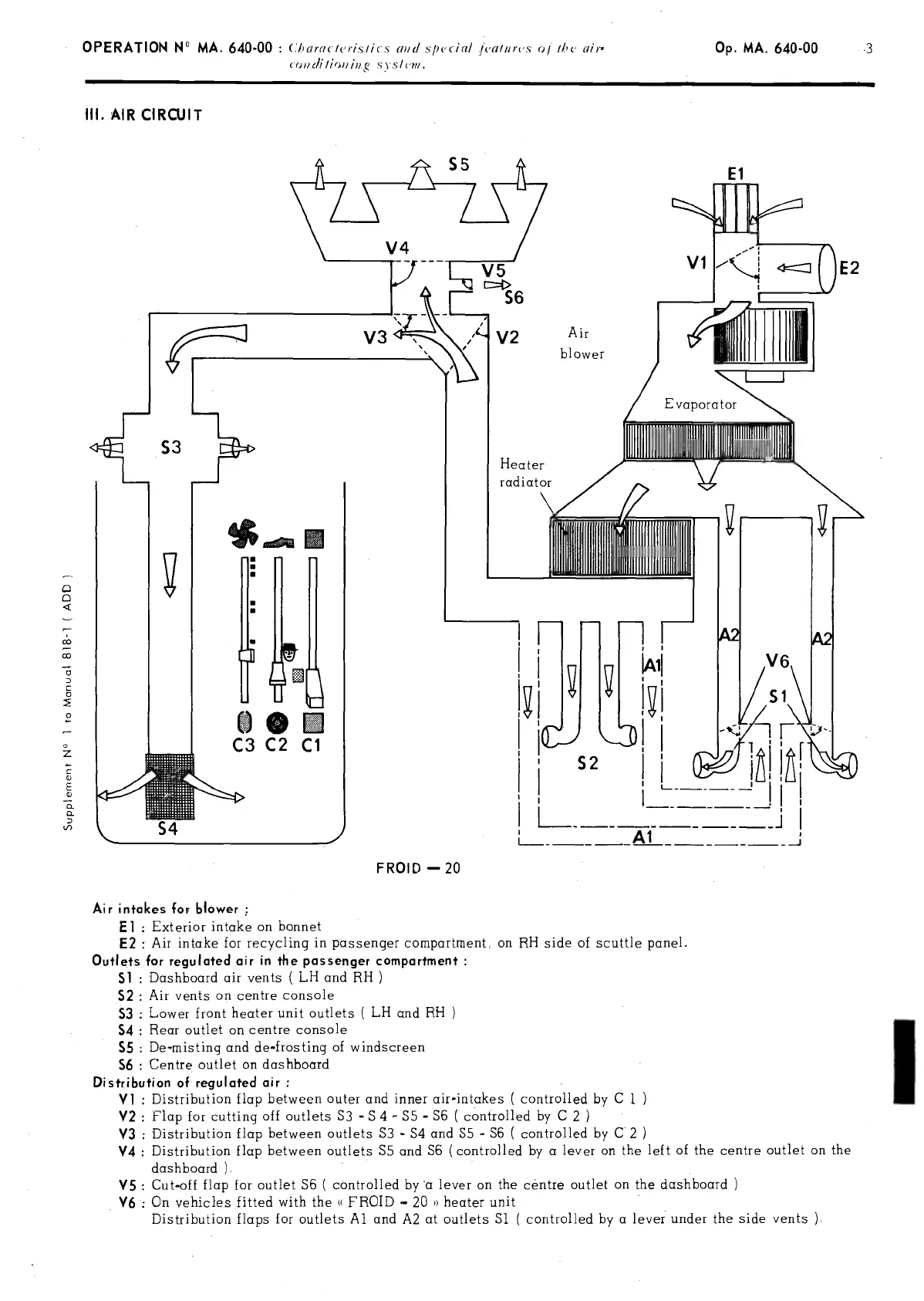
III.
AIR
CIRCUIT
0
0
4
co
co
0
0
0
0
z
0
cb
E
0
0
0
'fl
FROID
-20
1
1
L.
--
J
Air intakes
for
blower
El :
Exterior
intake on bonnet
E2 :
Air intoke for recycling
in
pcissenger compartrnent,
on
RH
side
of scuttle
panel.
Outlets
for
regulated
air
in
the
passenger compartment
Si:
Dashboord air
vents
(
LH ond
RH
S2 :
Air
vents
on
centre
console
S3
:
Lower
front
heoter
unit outlets
(
LH
and
RH
S4
:
Reor outlet on centre
console
S5
:
De-niisting
ond de-frosting
of windscreen
S6
:
Centre
outlet
on
dashboord
Distribution
of regulated
air
Vi :
Distribution flap between
outer and
inner
air-intakes
(
controlled by 0
1
V2
:
Flap for
cutting
off
outlets
S3
-
S 4
S5
-
SS
(
controlled by C
2
V3 :
Distribution flap between
outlets
S3
-
S4
and
S5
-
SS
(
controlled
by
C
2
V4
:
Distribution flap between outlets S5 and
S6 (controlled by a lever
on
the left
of
the
centre
outlet on the
doshboard
).
V5
:
Cut-off
flap for outlet S6
(
controlled by
a lever
on
the
céntre outlet
on
the
dashboard
V6:
On
vehicies
1
itted with the
«
FROID
20
»
heater unit
Distribution
flaps
for
outlets Al
and
A2 at outlets Si
(
controlled by o
lever
under the
side vents
).
PDF compression, OCR, web-optimization with CVISION's PdfCompressor

 Loading...