[SM-P00081-A]
−10−
1
PRODUCT
1.5 Switches and LED indicators
● Discharge static electricity from your body before touching the product.
Static electricity may cause damage to the product.
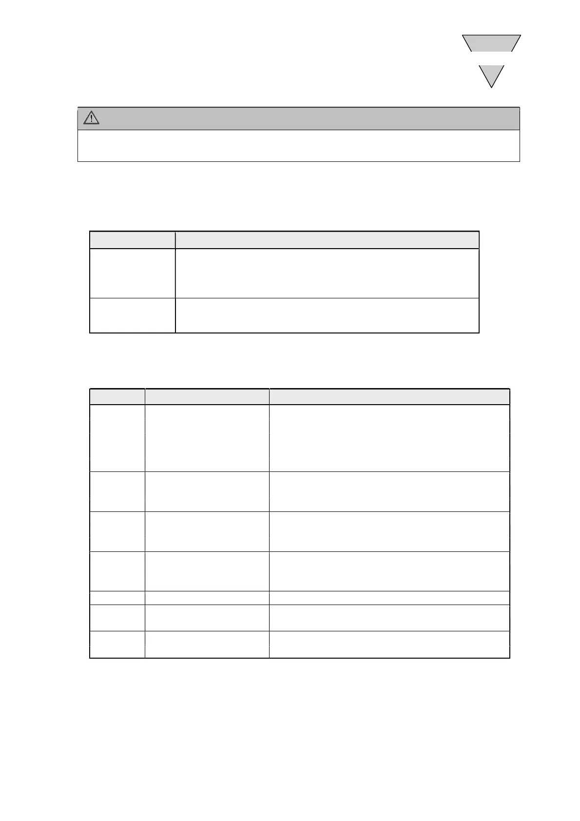
1) Switches
The switches are used to set the slave unit node address and the action taken on the output in the
event of a communication error.
This slave unit operates according to the switch settings when the power is on.
Switch Settings
Rotary switch
[Node address]
ID x16, x1
Set the slave unit node address between 01 to FF (Hex) [1 to 255 (Dec)].
Set the upper digit with x16, and the lower digit with x1.
The factory setting of the rotary switch is "00". To set the node address from
the master unit, set the rotary switch to "00".
Slide switch
[Output mode]
Select whether to hold (HLD) or clear (CLR) the output status when a
communication error occurs.
2) LED indicators
The LED indicators show the status of the network.
Refer to the following table for the description of LED indicators.
LED Function State
RUN EtherCAT State
OFF:
INIT
Green blinking:
PRE-OPERATIONAL
Green single flash:
SAFE-OPERATIONAL
Green flickering:
BOOTSTRAP
Green light:
OPERATIONAL
ERR Communication state
OFF:
Normal communication
Red double flash:
Communication error (WD time-out)
Red blinking:
Communication error
L/A IN EthetCAT IN link state
OFF:
No link
Green light:
Link detected but no activity
Green flickering:
Link and activity detected
L/A OUT EthetCAT OUT link state
OFF:
No link
Green light:
Link detected but no activity
Green flickering:
Link and activity detected
INFO Model discrepancy Red double flash:
Discrepant
PW Unit power state
OFF:
Unit power OFF
Green light:
Unit power ON
PW(V) Valve power state
OFF:
Valve power OFF
Green light:
Valve power ON
 Loading...