[SM-P00081-A]
−14−
3
OPERATION
3.3 Correspondence between Slave Unit Output Number and PLC Address Number
1) PLC address correspondence table
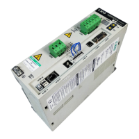
N4E0-T7EC1, N4E0-T7ECT1 (16-point output)
Assigned address
in the PLC memory
Output Bit 00 to 15
00 01 02 03 04 05 06 07 08 09 10 11 12 13 14 15
slave unit
0 1 2 3 4 5 6 7 8 9 10 11 12 13 14 15
Solenoid output no.
s1 s2 s3 s4 s5 s6 s7 s8 s9 s10 s11 s12 s13 s14 s15 s16
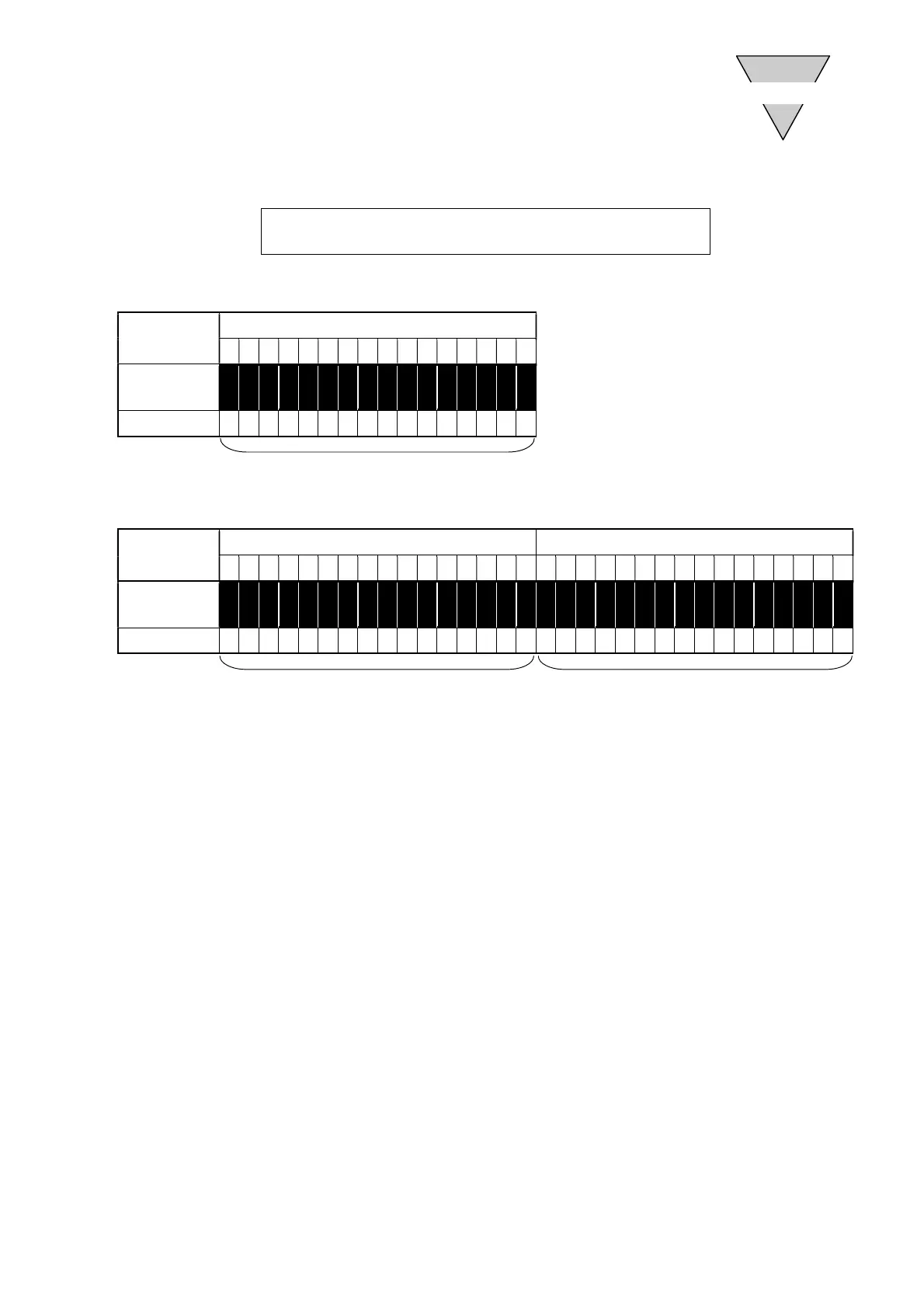
N4E0-T7EC2, N4E0-T7ECT2 (32-point output)
Assigned address
in the PLC memory
Output Bit 00 to 15 Output Bit 16 to 31
00 01 02 03 04 05 06 07 08 09 10 11 12 13 14 15 16 17 18 19 20 21 22 23 24 25 26 27 28 29 30 31
slave unit
0 1 2 3 4 5 6 7 8 9 10 11 12 13 14 15 16 17 18 19 20 21 22 23 24 25 26 27 28 29 30 31
Solenoid output no.
s1 s2 s3 s4 s5 s6 s7 s8 s9 s10 s11 s12 s13 s14 s15 s16 s17 s18 s19 s20 s21 s22 s23 s24 s25 s26 s27 s28 s29 s30 s31 s32
This correspondence table uses Omron’s PLC as an example.
The serial transmission slave unit address is set to "node address 1".
1-word output data
1-word output data
2-word output data
 Loading...