[SM-P00081-A]
―9―
1
PRODUCT
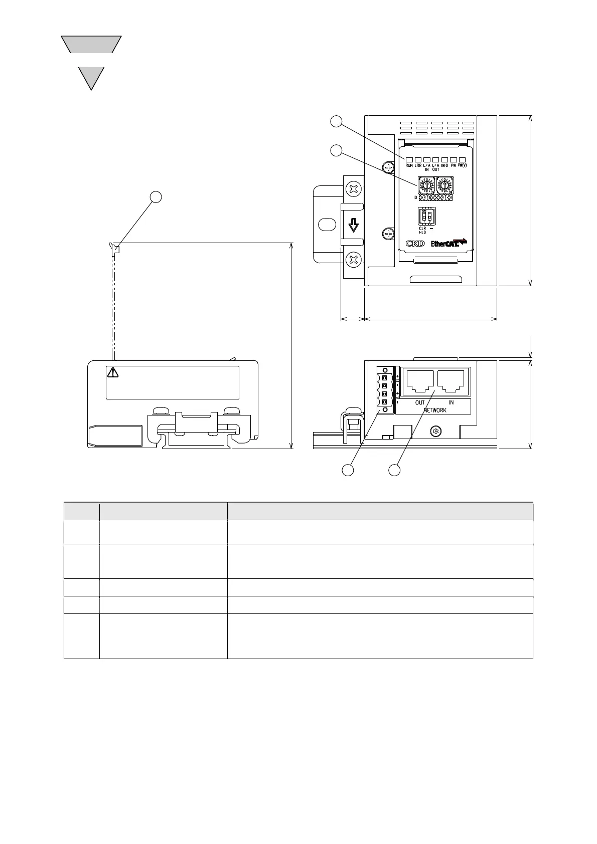
1.4 Slave unit parts
No. Part name Description
1 Monitoring lamp
Indicates the status of the slave unit and network with RUN, ERR, L/A IN,
L/A OUT, INFO, PW, and PW(V).
2 Setting switches
Rotary switch: Sets the slave unit node address.
Slide switch: Sets the action taken in the event of a communication error.
3 Cover Protects the monitoring lamps and setting switches.
4 Unit/valve power plug Connects the unit/valve power cables (24 V).
5
Network connector socket
(RJ45 × 2 ports [IN, OUT])
(Network connector plug is not
supplied.)
IN: Receives EtherCAT communication from the previous slave unit.
OUT: Sends EtherCAT communication to the next slave unit.
If the product is the end unit of the EtherCAT network, a network
plug is not connected to OUT.
 Loading...