17
6.11 MODBUS - RS485
6 - ELECTRIC CONNECTIONS
LED BSP communication with AP1 module
green communication ok
yellow software ok but communication with AP1
down
red flashing : software error
fixed : hardware error
LED BUS communication with MODBUS
green communication ok
yellow startup / channel not communicating
red communication down
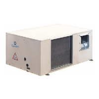
Every RS485 serial line must be set up using the 'In/
Out' bus system. Other types of networks are not
allowed, such as Star or Ring networks
The difference in potential between the earth of the
two RS485 devices that the cable shielding needs to
be connected to must be lower than 7 V
Suitable arresters must be set up to protect the serial
lines from the effects of the atmospheric discharges
A 120 ohm resistance must be located on the end of
the serial line. Alternatively, when the last serial
board is equipped with an internal terminator, it must
be enabled using the specific jumper, dip switch or
link
The cable must have insulation features and non-
flame propagation in accordance with applicable
regulations
The RS485 serial line must be kept as far away as
possible from sources of electromagnetic
interference.
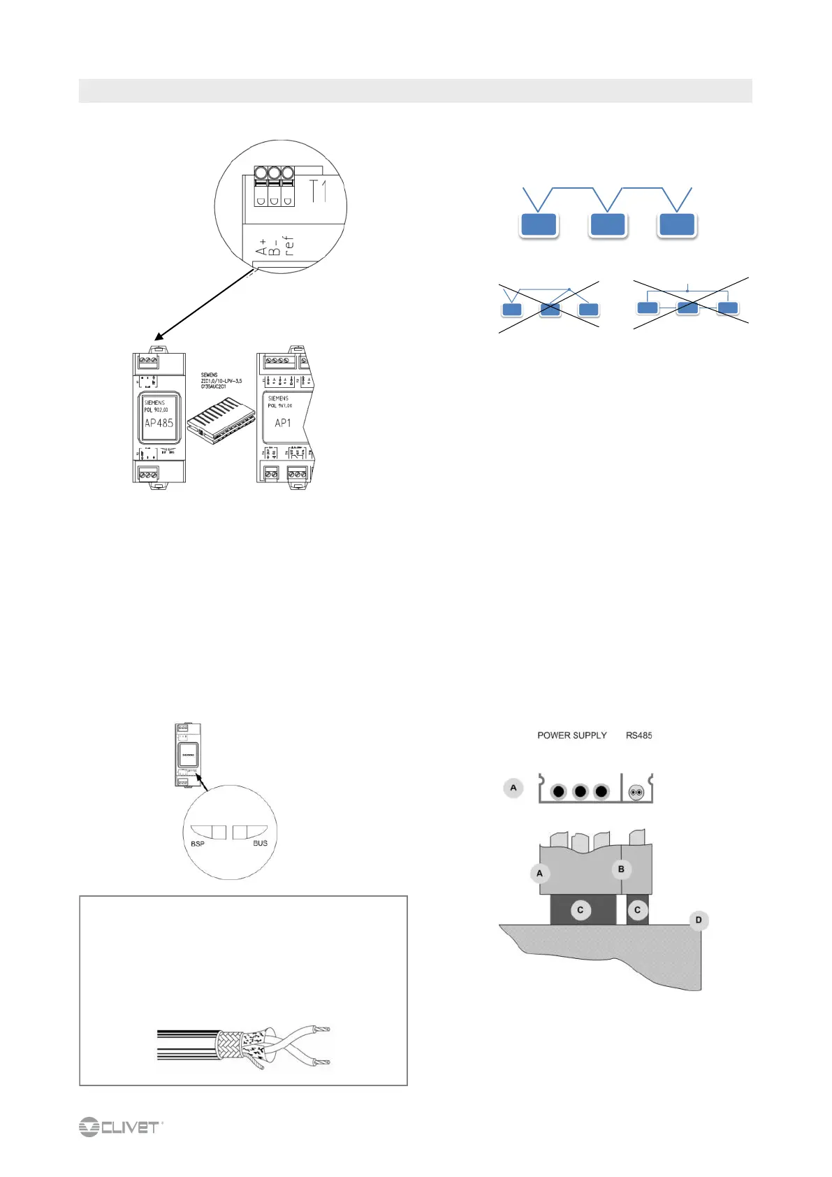
A metal conduit
B metal septums
C metal-lined sheath (sleeve)
D unit
CABLE MODBUS, BACNET, LONWORK REQUIREMENTS
Couple of conductors twisted and shielded
Section of conductor 0.22mm
2
…0,35mm
2
Nominal capacity between conductors < 50 pF/m
nominal impedance 120 Ω
Recommended cable BELDEN 3105A

 Loading...