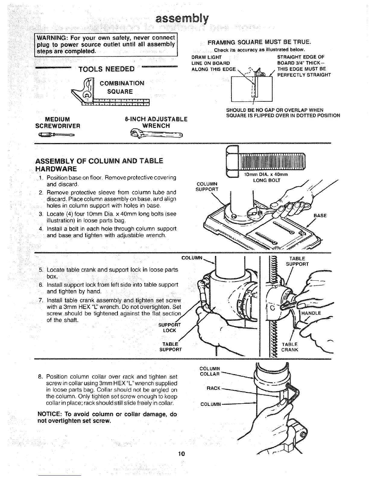
assembly
IWARNiNG: For your own safety, never connect
l plug to power source outlet until all assembly
I steps are completed.
- TOOLS NEEDED ......................
COMBINATION
SQUARE
MEDIUM 8-iNCH ADJUSTABLE
SCREWDRIVER WRENCH
-- 03
FRAMING SQUARE MUST BE TRUE.
Check its accuracy as illustrated below.
DRAW LIGHT
LINE ON BOARD
ALONG THIS X,,,.__ ,_ //
EDGE '_',
J
SHOULD BE NO GAP OR OVERLAP WHEN
SQUARE IS FLIPPED OVER IN DOTTED POSiTiON
STRAIGHT EDGE OF
BOARD 3/4" THICK--
THIS EDGE MUST BE
PERFECTLY STRAIGHT
ASSEMBLY OF COLUMN AND TABLE
HARDWARE
1. Position base on floor, Remove protective covering
and discard
2. Remove protective sleeve from column tube and
discard. Place column assembly on base. and aligr
holes in column support with holes Ln oase,
3, Locate (4) four lOmm Di& x 40mm long bolts (see
illustration) in loose parts bag.
4, Install a bolt in each hole through column support
and base and tighten with adjustable wrench.
1Omm DIA. x 40rnm
COLUMN LONG BOLT / _," /
soPpO.T . f /
COLUMN
5. Locate table crank and support lock in loose parts
bOX,
6. Install support lock from left side into table support
and tighten by hand.
7. Install table crank assembly and tighten set screw
with a 3mm HEX "E'wrench, Do not overtighten. Set
screw should be tightened against the flat section
of the shaft.
SUPPORT
LOCK
TABLE
SUPPORT
=L__/PTABLE
PORT
8. Position column collar over rack and tighten set
screw in collar using 3rnm HEX "L" wrench supplied
in loose parts bag. Collar shou d not be angled on
the column. Only tighten set screw enough to keep
collar _nplace: rack should still slide freely in collar
COLUMN
COLUMI
NOTICE: To avoid column or collar damage, do
not ovettighten set screw.
10
 Loading...