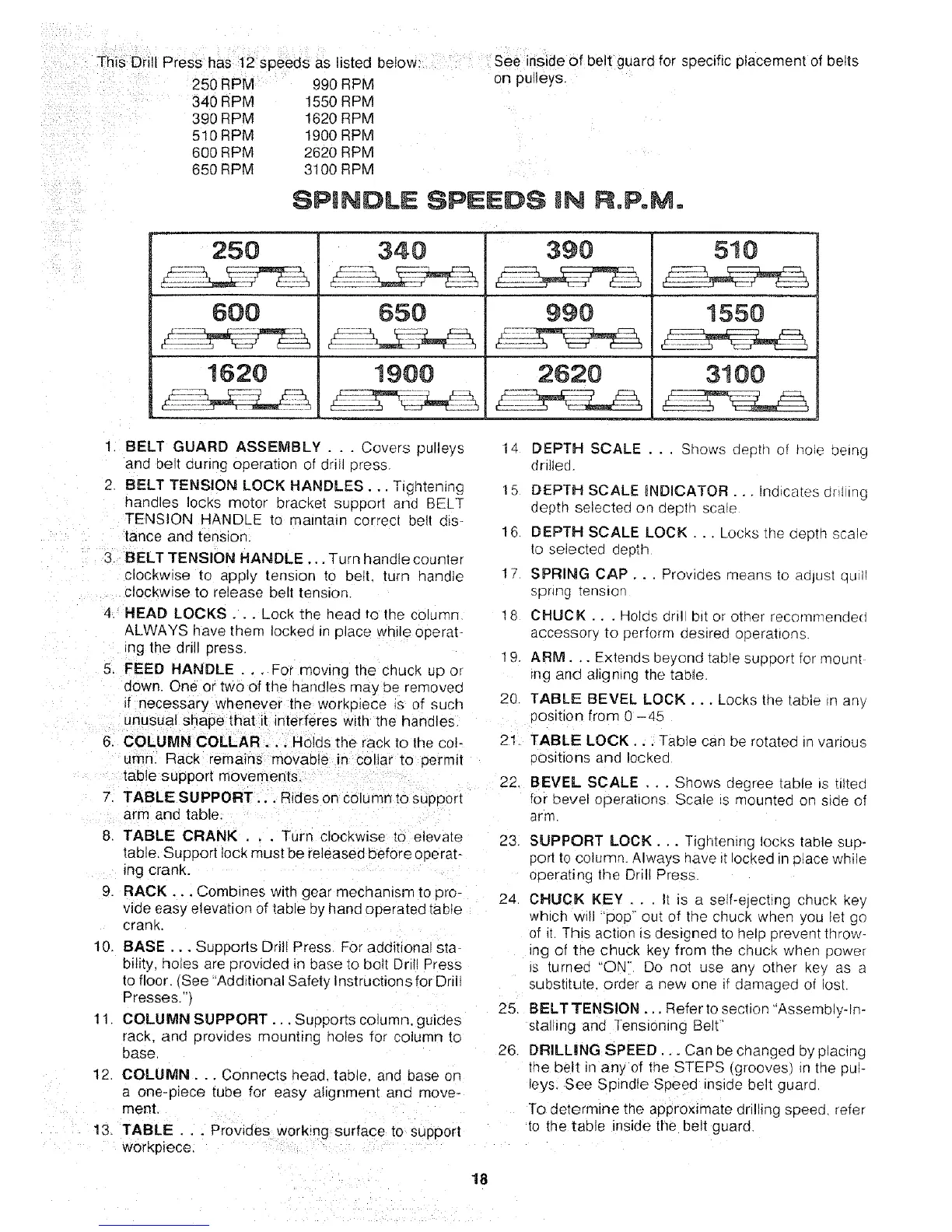
T_I_ Diili Press has t2 sp_ed_ as listed belowi : see inside of be!t guard for specific placement of belts
.... o_n_...,u,,,,,,D°_ 990 RPM on pulleys.
/ ii ¸
i_i,_ii_i_ii '_i_ i_i
340 RPM 1550 RPM
390 RPM 1620 RPM
510 RPM 1900 RPM
600 RPM 2620 RPM
650 RPM 3100 RPM
SPINDLE SPEEDS IN RoPoMo
250
600
1620
340
650
1900
390
990
2620
510
1550
3!00
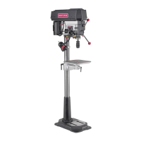
1. BELT GUARD ASSEMBLY . . . Covers pulleys
and belt during operauon of drill press.
2 BELT TENSION LOCK HANDLES... Tightening
handles locks motor bracket support and BELT
TENSION HANDLE to maintain correct be!t dtS-
tance and tenston.
3, BELT TENSION HANDLE ... Turn handle counter
clockwise to apply tension to belt. turn handle
clockwise to release belt tension.
4. HEAD LOCKS... Lock tne head to the column
ALWAYS qave thenq locked in place while operab
_ng the drill press
5. FEED HANDLE . . . For moving the chuck up or
down, One or two of the handles may oe removeo
if necessary whenever the worKo_ece _s of such
unusual shape that it interferes w_th the handles
6. COLUMN COLLAR ... Holds the rack to the col-
umn. Rack remafns movable in collar to permit
table support movements.
7. TABLE SUPPORT,.. Rides on column to support
arm and table.
8. TABLE CRANK . . . Turn clockwise to elevate
table. Support lock must be released before operat-
ing crank.
9 RACK... Combines with gear mechanism to pro-
vide easy elevation of table byhand operated table
crank
10.
BASE... Supports Drill Press For additional sta-
bility, holes are provided in base to bolt Dril Press
to floor. {See 'Additional Safety Instructions for Drill
Presses.q
11 COLUMN SUPPORT... Supports column, guides
rack. and provides mounting holes for column to
ease
12. COLUMN... Connects iqead, table, ana ease on
a one-piece tube for easy alignment and move-
ment.
13. TABLE . . . Provides working surface to support
workpiece.
DEPTH SCALE . .. Shows depth of hope being
drllleo.
14
15 DEPTH SCALE _NDICATOR... Indrcates dr_t ing
depth selected on depth sca=e
16 DEPTH SCALE LOCK... Locks :no oepth scale
to selected aeoth
1• SPRING CAP... Provides means to adjust qu_ll
spnng _ension
18 CHUCK... Holc_s dril b_t or otlqer recornnended
accessory to perform posited operations
9. ARM... Extends oeyond tabte suDoort for mount
_ng ancJ ahgntng the table.
20. TABLE BEVEL LOCK... Locks the table Jn any
Position from 0 -45
21. TABLE LOCK... Table can be rotated in various
3ositions and poked
22. BEVEL SCALE ... Shows degree table is tiited
for bevel operahons Scale _s mounted on side of
arm.
23.
24
25
26
SUPPORT LOCK. . Tigntentng locks table sup-
port to column. Always have =tlocked in place while
operating the Dri Press.
CHUCK KEY . . . It is a self-ejechng chuck key
which wil "pop" out of tlqe chuck wnen you let go
of i[ This action is designed to help prevent throw-
ing of the chuck key from the cnuc_ when power
Js _urnec "ON" Do qot use any other key as a
substitute order a new one if damagea of iost
BELT TENSION,.. Refer to section "Assem 31y-In-
stalling and ]ension_ng Belt"
DRILLING SPEED... Can be changed by placing
the uelt in any of the STEPS tgroovesl n the puF
leys. See Spindle Speed inside belt guarG
To determine the ao#roximate drilling speed refer
to the table inside the belt guard.
18
 Loading...