RING MODULATOR, INPUTS; OSC2/SIN & OSC3/SIN
OUTPUT (Volts)
5.0
2.5
0.0
-2.5
-5.0
-7.5
3.00 4.00 5.00 6.00 7.00 8.00
Time (milliseconds)
7.5
RING MODULATOR, INPUTS; OSC2/SAW & OSC3/SQR
OUTPUT (Volts)
5.0
2.5
0.0
-2.5
-5.0
-7.5
3.00 4.00 5.00 6.00 7.00 8.00
Time (milliseconds)
7.5
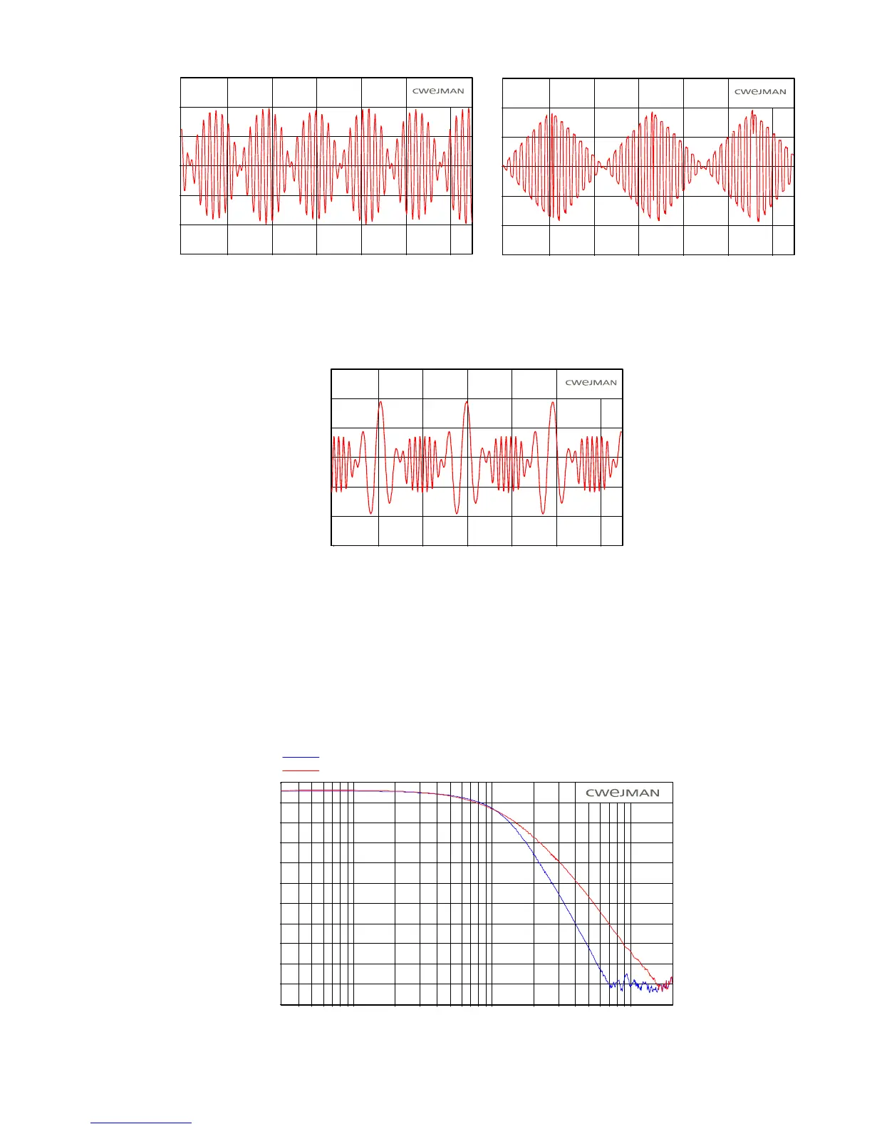
With synchronized oscillators a signal can be created with harmonic character but with the
characteristic ring modulator sound. In addition, if one of the oscillators is used to frequency
modulate the synchronized oscillator, the result can be as in the illustration below.
RING MODULATOR, INPUTS; OSC2/SIN & OSC3/SIN
OSC3 SYNC'ED and FREQUENCY MODULATED by OSC2
OUTPUT (Volts)
5.0
2.5
0.0
-2.5
-5.0
-7.5
3.00 4.00 5.00 6.00 7.00 8.00
Time (milliseconds)
7.5
LOW PASS FILTER
the foremost tool for sound modification.
The Low Pass Filter is a 6-pole construction. The reason for this is as follows; the slope of the filter
must be as steep as possible to provide the greatest filter effect. However, since it is obviously not
always desirable to use a filter with a steep slope, the LPF is equipped with a switch that enables
for both modes.
The sound processor with greatest effect is the Low Pass Filter and every synthesizer has at least one as
selection of either 6-pole or 4-pole operation. The illustration below shows the LPF frequency response
dBV rms
0.0
-10.0
-20.0
-30.0
-40.0
-50.0
-60.0
-70.0
-80.0
-90.0
-100.0
-110.0
30 50 70 100 200 300 500 1.0k 2.0k 5.0k 10.0k
Frequency (Hz)
LOW-PASS FILTER, Q-PEAK = 0
4-POLE MODE
6-POLE MODE
20.0k
40