DMS-1250 Series Multi-G Ethernet Smart Managed Switch Hardware Installation Guide
7
Feature Description
5 Type 3 (802.3bt) Max Power used by PD:
51 Watt
• The total PoE power budget of DMS-1250-10SP/12TP : 240 W.
• The total PoE budget of DMS-1250-10SPL: 120 W.
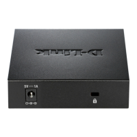
Rear Panel Components
The rear panel of this switch features a security lock, a GND, an AC power connector, and a power cord retainer hole.
Figure 1-5 DMS-1250-10S
Figure 1-6 DMS-1250-10SP
Figure 1-7 DMS-1250-12TP
Figure 1-8 DMS-1250-10SPL
Components that can be found on the rear panel of this switch are listed in the table below.
Component Description
Security Lock Provide a Kensington-compatible security lock to be able to connect to a secure
immovable device. Insert the lock into the notch and turn the key to secure the
lock. The lock-and-cable apparatus should be purchased separately.
Switch GND Use an electrical grounding wire and connect one end of the wire to the Switch
GND and the other end of the wire to an electrical grounding point most commonly
found on the Switch mounting rack itself.
AC or DC power connector Use with AC power cord or external power adapter to supply power to the switch.
Power Cord Retainer The power cord retainer is used to fix the AC power cord in place and not easily
loose. For DMS-1250-10S/DMS-1250-10SP/DMS-1250-12TP)
Note: DMS-1250-10SPL DC power connector is in front panel.
 Loading...