SiUS121632EA Indoor Unit
Printed Circuit Board Connector Wiring Diagram 21
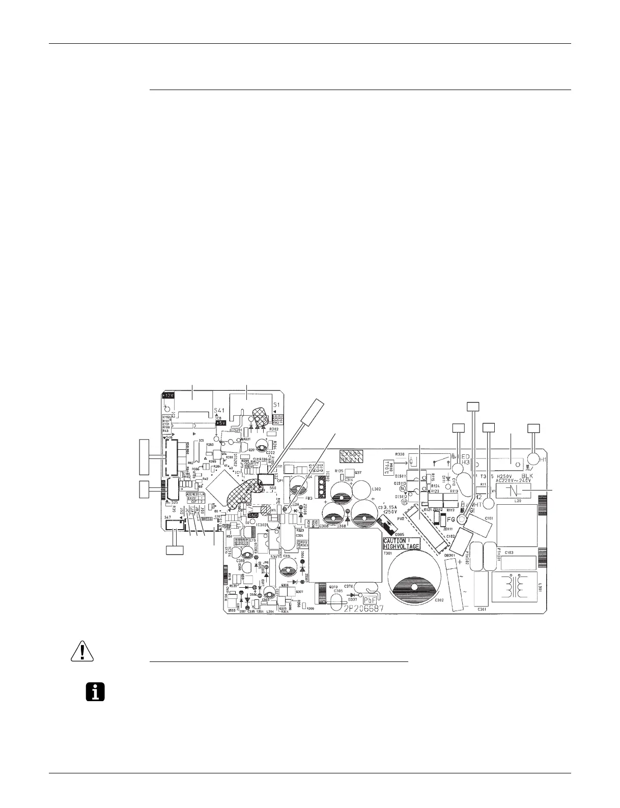
1.2 CTXS07LVJU, FTXS09/12LVJU
Control PCB
(PCB1)
Caution Replace the PCB if you accidentally cut a wrong jumper.
Jumpers are necessary for electronic circuit. Improper operation may occur if you cut any of them.
Note: The symbols in the parenthesis are the names on the appropriate wiring diagram.
1) S1 Connector for DC fan motor
2) S21 Connector for centralized control (HA)
3) S25 Connector for INTELLIGENT EYE sensor PCB (PCB4)
4) S32 Indoor heat exchanger thermistor
5) S41 Connector for swing motors
6) S46 Connector for display PCB (PCB3)
7) S47 Connector for signal receiver PCB (PCB2)
8) H1, H2, H3, FG Connector for terminal strip
9) JA Address setting jumper
∗ Refer to page 215 for details.
10)JB Fan speed setting when compressor stops for thermostat OFF
∗ Refer to page 217 for details.
11)JC Power failure recovery function (auto-restart)
∗ Refer to page 217 for details.
12)LED A LED for service monitor (green)
13)FU1 (F1U), FU2 (F2U) Fuse (3.15 A, 250 V)
14)V1 Varistor
V1
FU1
S1S41
S21
S47
JB
JA
JC
S46
S25
LED A
FU2
S32
FG
H1H2H3
2P206687-4
 Loading...