SiUS121632EA Wireless Remote Controller Kit
Printed Circuit Board Connector Wiring Diagram 31
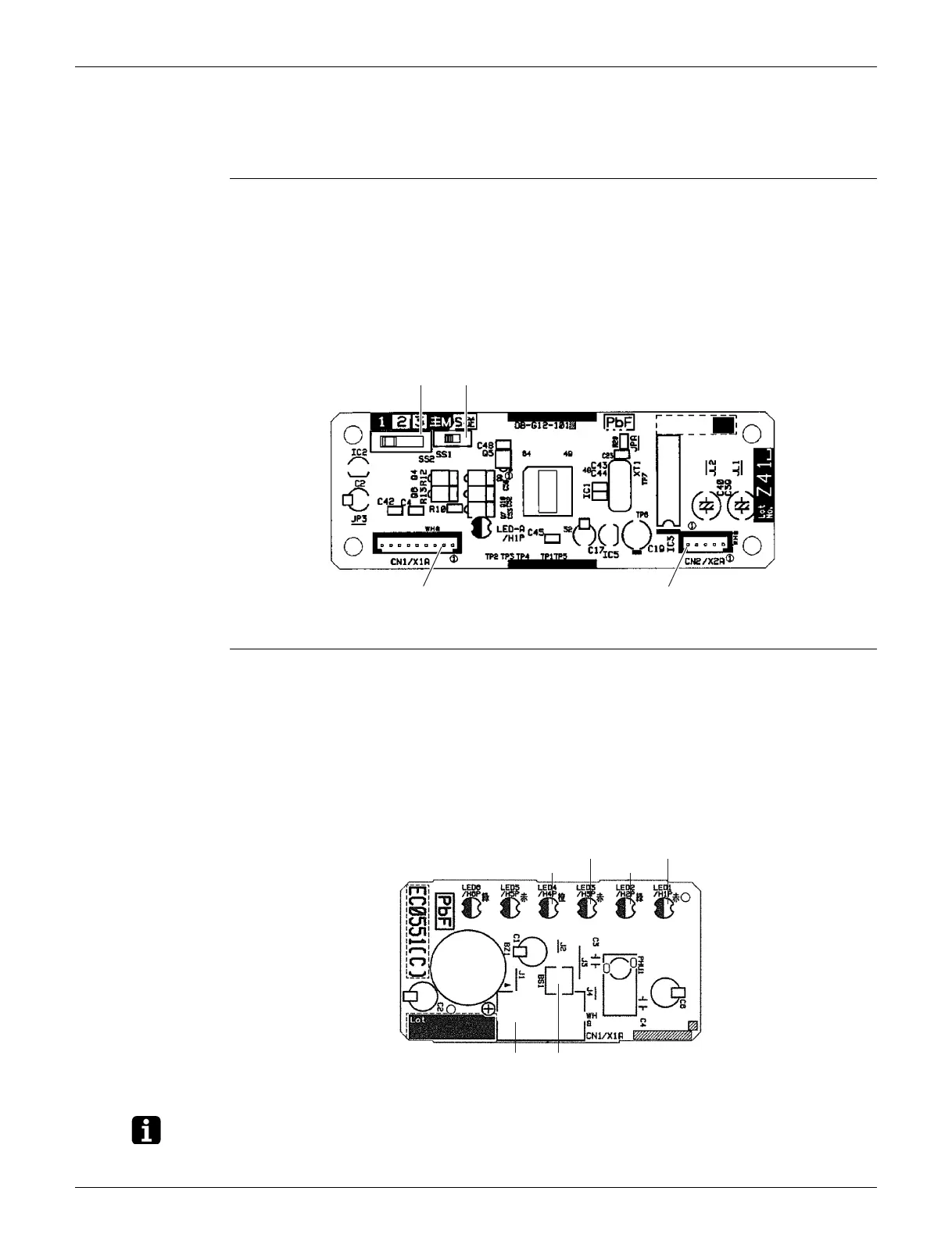
3. Wireless Remote Controller Kit
3.1 BRC082A41W, BRC082A42W(S)
Transmitter
Board (A2P)
Receiver (A3P)
LED5 and LED6 do not function.
Note: The symbols in the parenthesis are the names on the appropriate wiring diagram.
1) X1A Connector for receiver (A3P)
2) X2A Connector for control PCB (A1P)
3) SS1 MAIN/SUB setting switch
∗ Refer to page 223 for details.
4) SS2 Address setting switch
∗ Refer to page 223 for details.
3P156326-3
X2A
SS2
SS1
X1A
1) X1A Connector for transmitter board (A2P)
2) BS1 Emergency operation switch
3) LED1 (H1P) LED for operation (red)
4) LED2 (H2P) LED for timer (green)
5) LED3 (H3P) LED for filter cleaning sign (red)
6) LED4 (H4P) LED for defrost operation (orange)
3P174795-1
LED 4
X1A BS1
LED 3
LED 2
LED 1
 Loading...