23
Handling
Useful
Functions
Monitor Items
When the “Monitor mode” is selected, the following items can be checked.
∗1: Nos. 0, 1, 2, and 3 indicate a temperature detected with each thermistor.
When the relevant thermistor is not connected or has a wire break, “–99.9” is displayed.
∗2: With the factory setting, “O” is displayed. However, the indication will become valid when the parameter n020 is "1" or optional communication
expansion board is installed.
∗3: The outlined calculation value is set under the conditions; power supply voltage 200 V and pump discharge pressure: 0.2 MPa (VG32: oil
temperature 25˚C). (The error is approximately 20%.)
For a machine without a pump, contact us separately.
No. Description Note
∗1
∗1
–
–
∗3
∗2
∗1
∗1
∗1
∗1
0
5
6
7
8
9
1
2
3
4
When the data number is changed, the temperature
currently detected with the thermistor and input/output
values simultaneously appear on the data display.
Machine temperature [Th1]
Outlet oil temperature or returned oil temperature [Th2]
Room temperature [Th3]
Inlet oil temperature [Th4]
Reserve [Th5]
T (Th4–Th2)
Capacity command value (%)
Compressor inverter rotation speed (rps)
Power consumption (kW)
∗
Status of expansion DIN (third digit)/DOUT (second digit)
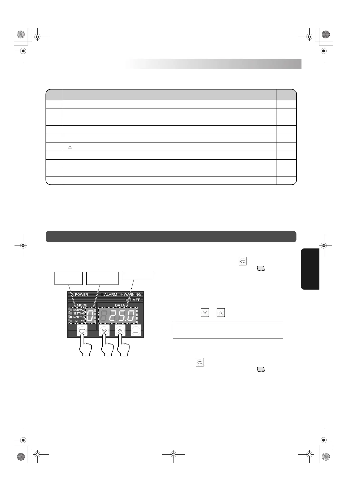
• Go to the monitor mode with the key.
See “Mode changing operation” on page .
• The “MONITOR” lamp on the operation mode indicator lights.
∗ The value on the data number display blinks.
• Press the key two times, to return to the normal mode.
See “Mode changing operation” on page .
• The “NORMAL” lamp on the operation mode indicator lights.
1. Select the monitor mode.
2. Monitor the current status.
3. Return to the normal mode.
Operating procedure
Change the value on the data number display to a desired
value with the or key.
17
17
Data displayData number
display
Operation mode
indicator
1·3 2 2
PIM00318A_EN.fm Page 23 Tuesday, October 26, 2010 12:37 PM
 Loading...