33
Alarm/Warning Output Logic
Alarm Settings for Optional Protection Devices (Installed by User)
The Oil Cooling Unit can output an operation status signal to the main machine through wiring to the signal terminal block and
parameter setup.
1. Connect the required signal cable to the signal terminal block.
(For the connecting method, refer to “Connection of external output contact” on page .)
2. Set Parameter [n001].
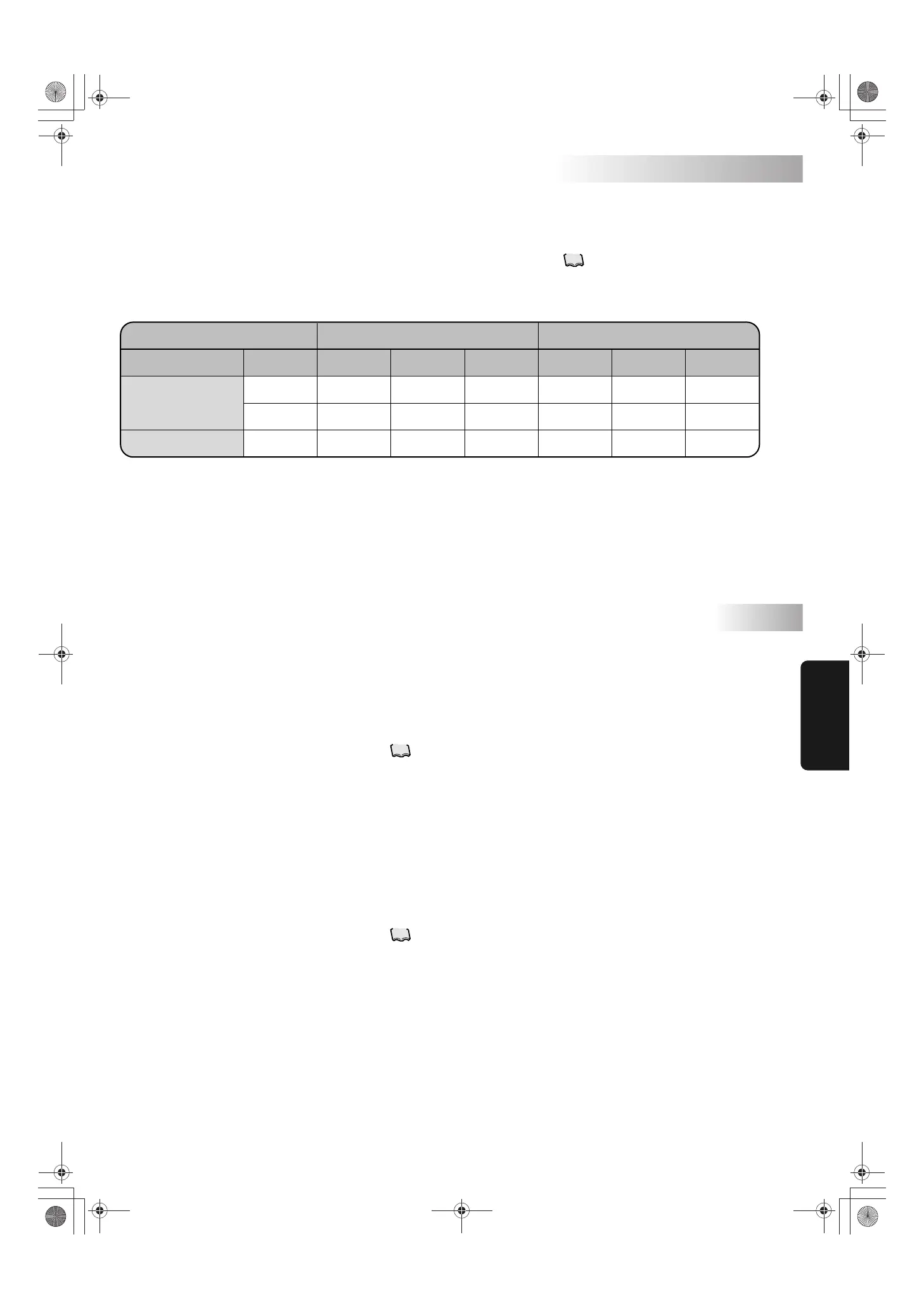
n001: Alarm/warning output logic (First digit).
Setting 0 1 (2 to 9: Same operation as with 1)
60–61
60–63
66–67
ON
OFF
ON
OFF
ON
OFF
OFF
ON
OFF
OFF
ON
OFF
OFF
ON
OFF
ON
OFF
ON
Contact Normal
Power failure
Alarm Normal
Power failure
Alarm
Alarm output
Warning output
First digit: Specifies alarm output logic (60-61, 60-63) and warning output logic (66-67) of the signal terminal block.
Second digit: Specifies DOUT signal output logic. (Optional communication expansion board is required.)
The Oil Cooling Unit can activate an alarm by receiving an output signal from optional protection devices (e.g. flow switch,
level switch).
When using OP terminals [12] and [13]:
1. Connect the signal cable of the optional protection device to terminals [12] and [13] on the Oil Cooling Unit signal terminal
block.
(See “Outline of electrical equipment box” on page .)
2. Set Parameter [n002].
“0”: OP terminal is not used. (Factory setting)
“1”: When OP contact turns OFF, Alarm Level 1 is activated.
“2”: When OP contact turns OFF, Alarm Level 2 is activated.
“3”: When OP contact is not ON after 30 seconds from pump operation start, Alarm Level 1 is activated.
(When flow switch is used)
[CAUTION]
The protection function cannot be activated simply by connecting the protection device to the OP terminals.
Be sure to set this parameter.
When using OP 2 terminal [CN2]:
1. Connect the signal cable of the optional protection device to [CN2] on the Oil Cooling Unit control board.
(See “Outline of electrical equipment box” on page .)
2. Set Parameter [n003].
“0”: OP2 terminal is not used. (Factory setting)
“1”: When OP2 contact turns OFF, Alarm Level 1 is activated.
“2”: When OP2 contact turns OFF, Alarm Level 2 is activated.
[CAUTION]
The protection function cannot be activated simply by connecting the protection device to the OP terminals.
Be sure to set this parameter.
11
10
10
Handling
Useful
Functions
PIM00318A_EN.fm Page 33 Tuesday, October 26, 2010 12:37 PM
 Loading...