4-14
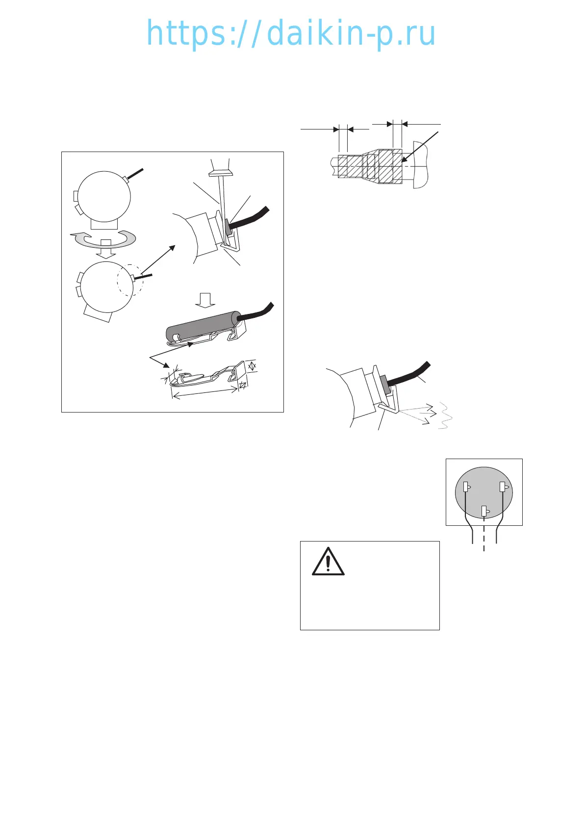
5. Pull compressor out to front, turn the body
approximately 20°clockwise and remove DCHS2
sensor mounted on right side. (Fig. 5)
Hitch a screw driver to the cramp of spring plate
to pull out the sensor. (Fig. 6)
Spring plate
2
40
5
5
Fig. 5
Top view of compressor
DCHS2
Screw driver
cramp
(Spring plate)
Fig. 6
●Compressor installation
1. Temporarily placing the compressor
Temporarily tighten the four bolts at the compressor
base and the one bolt at the compressor top.
2. Connecting
Discharge, suction and injection pipes
2-1.
Place the provided packing on the discharge and
suction pipe connecting ports of the compressor.
2-2.
After temporarily tightening lock nuts and flare
nuts for three pipes, finally tightening them one by
one to connect the pipes.
Use two wrenches for the final tightening of flare
nuts so as not to damage the pipes (figs. 3 & 4).
2-3. Tightening torque for lock nut and flare nut is
based on following.
Discharge pipe: 122N・m (1244.1kgf・cm)
Suction pipe: 122N・m (1244.1kgf・cm)
Injection pipe: 54.9N・m (559.8kgf・cm)
2-4. Apply silicon to cover each lock nut after
tightening.
10mm or more
10mm or more
Fully apply silicon
sealant to the entirety
of the parts indicated
with diagonal lines to
prevent the entry of
water into the discharge
and suction pipes.
Fig. 7
4. Fixing the compressor
After connecting the pipes, finally tighten the four
bolts to secure the compressor base and the
one bolt to secure the compressor top to fix the
compressor.
5. Installing DCHS2 sensor
Insert an assembled item consisting of the
DCHS2 sensor and the spring plate until the
cramp sound (Fig. 8).
Fig. 8
DCHS1
Click (sound)
Cramp (Spring plate)
6. Connecting the compressor
cables
Correctly connect the
compressor cables as per the
Terminal Wiring Procedure
attached to the compressor.
Caution
Wrong wiring will reverse
the compressor and result
in compressor damage.
Black
White
Red
Fig. 9
Wiring terminal
U
V
W
04章LX10F11B3TR16-02En.indd4-1404章LX10F11B3TR16-02En.indd4-14 2016/02/0316:22:072016/02/0316:22:07
 Loading...