4-27
A
B
C
D
E
B
A
C
D
E
X6A
(CPU board)
1
2
3
4
5
6
7
8
A
B
C
A
B
C
A
B
C
A
B
C
CTR(CTS)
UR3(USDA3)
UR2(USDA2)
UR1(USDA1)
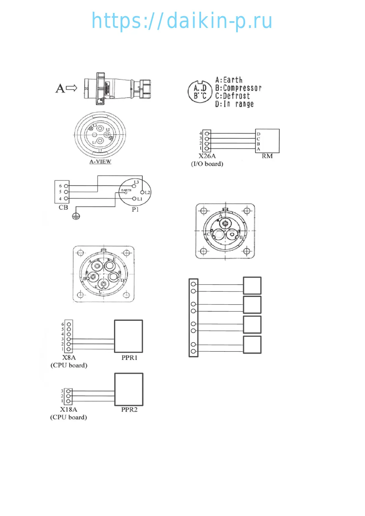
4.10 External Receptacle Wiring Diagrams
4.10.1 Power Plug (P1)
●Layout
4.10.3
Remote Monitoring Receptacle (RM; option)
●Layout (as seen from the front)
4.10.4
USDA Sensor 1 to 3 Receptacles (USDA 1 to 3; options)
Cargo Temperature Sensor Receptacle (CTR; option)
●Layout (as seen from the front)
●Wiring diagram
●Wiring diagram
4.10.2
PC Port Receptacle (PPR1, 2)
●Layout (as seen from the front)
●Wiring diagram
●Wiring diagram
04章LX10F11B3TR16-02En.indd4-2704章LX10F11B3TR16-02En.indd4-27 2016/02/0316:22:162016/02/0316:22:16
 Loading...