4-3
RM Circuit Check
ESC : Cancel
Connect Remote
Monitor Plug
Then Press Enter
RM Circuit Check
RM-Comp Circuit Check
RM-Defrost Circuit Check
RM-In Range Circuit Check
RM-Compressor Check
ESC OFF and Return
▲▼ : Change
ENTER : Confirm
OFF
RM-Compressor Check
ESC : OFF and Return
▲▼ : Change
ENTER : Confirm
ON
1/1
Normal
ESV
SV 1
SV 2
RM
R/F
ESV
SV 1
SV 2
RM
R/F
Error
I/O board
Manual Check
NEXT
PREV
2/3
RM ON/OFF
Comp ON/OFF
HuS-reading
All Sensor Calibration
----------
Follow the same procedure for other magnetic contactor or solenoid valve ON/OFF check.
※2 PCC2 ON/OFF Check
※3 CFH & PCC1 (or 2) ON/OFF Check
※4 CFL & PCC1 (or 2) ON/OFF Check
※5 EFH & PCC1 (or 2) ON/OFF Check
※6 EFL & PCC1 (or 2) ON/OFF Check
※7 HSV ON/OFF Check
※8 RSV ON/OFF Check
※9 LSV ON/OFF Check
※10 ESV ON/OFF Check
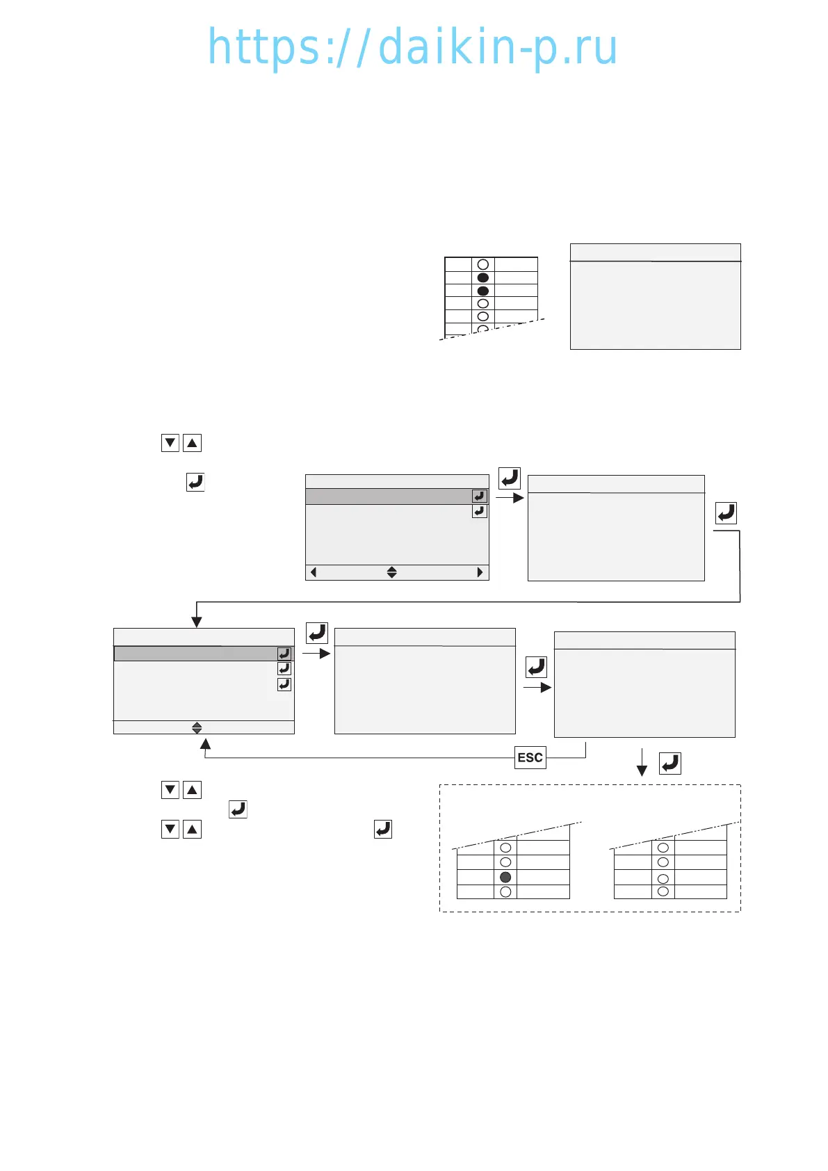
※11 RM (Remote Monitoring) Circuit Check (Option)
Follow the same procedure for RM-Defrost Circuit and RM-In Range Circuit checks.
※11-2 RM-Defrost Circuit Check
※11-3 RM-In Range Circuit Check
※11-1 RM-Compressor Circuit Check
1. Press key to
select "RM-ON/OFF"
and press key to
determine.
2. Connect Remote
Monitoring plug.
1. Press
key to select RM-Compressor
Check and press key to determine.
2. Press
key to select ON and press key
to determine. RM I/O Board LED "ON" for fail or
"OFF" for pass.
3. It is error when LED (Red) for RM lights ON. (RM
circuit for compressor is shorted.)
It is normal when the LED lights OFF.
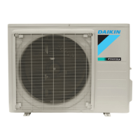
During checking, the
corresponded magnetic
contactor or solenoid valve
is energized and LED (I/O
board) lights ON (green).
During checking ※3〜
※6, the corresponded fan
operation current will be
displayed.
PCC1
PCC2
CFH
CFL
EFH
CFH &PCC2 ON
CFH & PCC2 ON
Current 2.2A
▲▼ : Change
ENTER : Confirm
ON
I/O board
CFH &PCC2 ON
04章LX10F11B3TR16-02En.indd4-304章LX10F11B3TR16-02En.indd4-3 2016/02/0316:21:582016/02/0316:21:58
 Loading...