OM 1077-1 • MAVERICK I 12 www.DaikinApplied.com
unIT InsTallaTIon
Indoor Relative Humidity Sensor
Field-congurable Input #2 can be used to connect an indoor
relative humidity sensor that has a 0–10Vdc output for a
0–100% indoor relative humidity input. Units with the optional
dehumidication control require this indoor relative humidity
sensor to operate the optional hot gas reheat coil. Because this
is a “powered” sensor, an additional wire to the 24Vac power
supply from the unit is required. The “R” thermostat input can
be used for this purpose. The indoor relative humidity sensor
can be used along with thermostat control, a zone sensor with
a time clock, or the BAS communication card and a third-party
BAS that will be controlled from a central location.
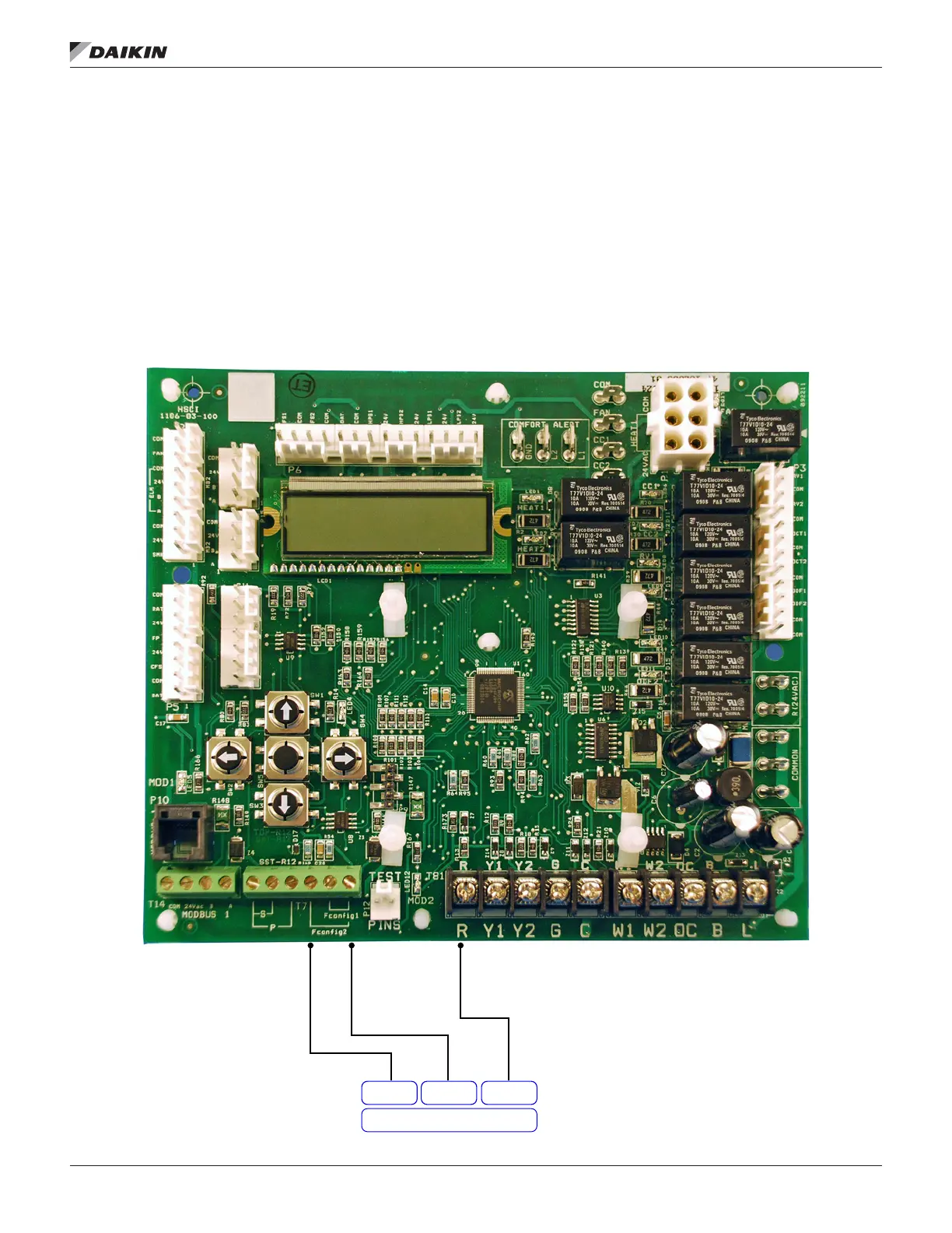
Figure 6: Indoor Relative Humidity Connection
Out Com 24VDC
Humidity Sensor
 Loading...