IM 915-13 • VISION - EXTENDED SIZES 28 www.DaikinApplied.com
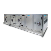
Daikin Applied Fan Array
Closing the damper on an operational fan could send the fan
into surge that could produce fans stall, excessive vibration,
unit damage, or personnel injury.
The Daikin Applied Fan Array is available with optional, factory
mounted VFDs. See OM manuals OM 1190 and 1191 for
details on the Daikin Applied supplied VFD.
Care should be taken when programing and synchronizing the
drives in the Daikin Applied Fan Array such that all fans turn at
the same speed. Fans running at unequal speeds can produce
vibration and could stall a fan. Denition of fan numbering is
given in Figure 44.
The Daikin Applied Fan Array is standard with a manual block
o plate. The unit will ship with one block o plate that will
come installed on fan 1A. This block o plate is to be removed
before unit operation and stored outside of the air tunnel. In the
event of a lost fan motor, the block o plate is installed on the
non-functional fan to prevent air re-circulation. This is designed
to be a temporary measure unit this fan and/or motor is
replaced. After fan and/or motor replacement the block o plate
is to be removed and stored outside of the air tunnel.
The Daikin Applied Fan Array has an optional gravity actuated
block o damper. These dampers are equipped with counter
weights.
The Daikin Applied Fan Array has an optional actuated block
o damper. These dampers are designed to prevent air
recirculation in the event of a lost fan. Care should be taken
that the damper actuator only be given a close signal if the fan
is not operational (motor burnout for example).
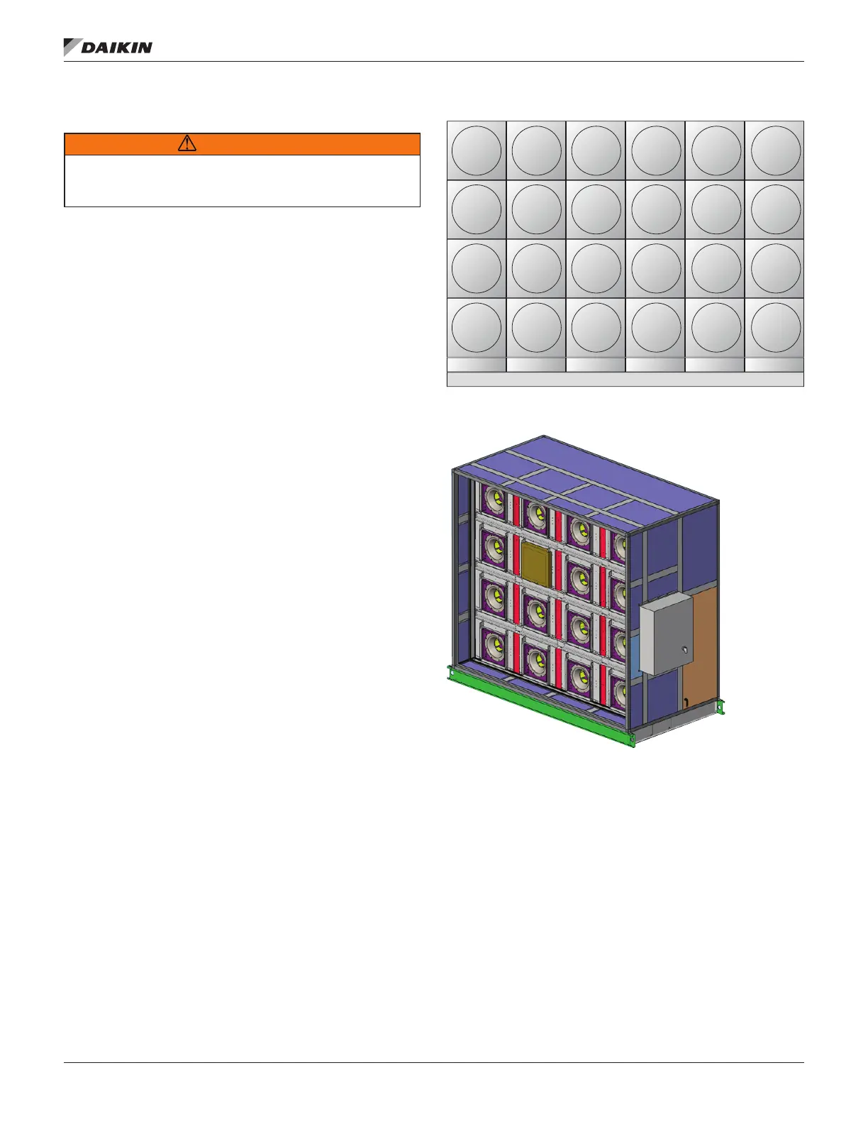
The Daikin Applied Fan Array can be equipped with a fan blank
o plate. See Figure 45 with a block o plate mounted to fan
3C. If the unit is ordered with the manual block o plate, it will
be installed to fan 1A. This plate has to be removed before
start up.
Figure 44: Daikin Applied Fan Array Conguration
Figure 45: Fan Array with Block O Plate
6D
6C
6B
6A
Viewed from Fan Inlet End
5D
5C
5B
5A
4D
4C
4B
4A
3D
3C
3B
3A
2D
2C
2B
2A
1D
1C
1B
1A
 Loading...