www.DaikinApplied.com 3 IM 915-13 • VISION - EXTENDED SIZES
General Information
Vision air handlers are not designed to be weather resistant.
Do not install them outdoors.
The system design and installation must follow accepted
industry practice as described in the ASHRAE Handbook, the
National Electric Code, and other applicable standards. This
equipment must be installed in accordance with regulations of
authorities having jurisdiction and all applicable codes.
Installation and maintenance must be performed by qualied
personnel familiar with applicable codes and regulations
and experienced with this type of equipment. Sheet metal
parts, self-tapping screws, clips, and other comparable items
inherently have sharp edges. The installer and maintenance
personnel should exercise caution.
Sharp edges and coil surfaces are a potential injury hazard.
Avoid contact.
Receiving and Handling
Inspection
• Carefully check items against the bills of lading to verify
all crates and cartons have been received. Carefully
inspect all units for shipping damage. Report damage
immediately to the carrier and le a claim.
Packaging
• All shipping wrap material, including stretch and shrink
wrap, must be removed upon unit arrival. This wrapping is
for transit protection only. Units are not to be stored with
wrapping material left on, as white rust will develop if any
moisture is present.
• Field-installed components will ship on separate skid(s).
• Hardware (screws, bolts, etc.) for assembling sections
are supplied in a bag attached to each section. All
necessary gasketing is applied in the factory for section-
to-section mounting. NOTE: A special #30 Torx bit is
required for assembly.
• Every shipping section includes a nameplate identifying
the customer tagging information, unit serial number,
unit order number, and the shipping section position for
installation.
Handling
• Vision air handler units are constructed of painted or
galvanized steel and are inspected thoroughly before
leaving the factory. Take care during installation to
prevent damage to units. Do not stand or walk on top of
units.
• Air handler bases are designed with the necessary
number of lifting points for safe installation. All lifting
locations must be used. See Rigging.
• Take special care when handling blower sections. All
fans are dynamically balanced before leaving the factory.
Rough handling can cause misalignment or a damaged
bearings or shaft. Carefully inspect fans and shaft before
unit installation to verify this has not happened.
• Handle the zone damper of the multi-zone units with
special care. Zone dampers are set and inspected before
leaving the factory but should be checked on arrival to the
job to verify the bell arm and connecting rod set screws
did not become loose in shipment.
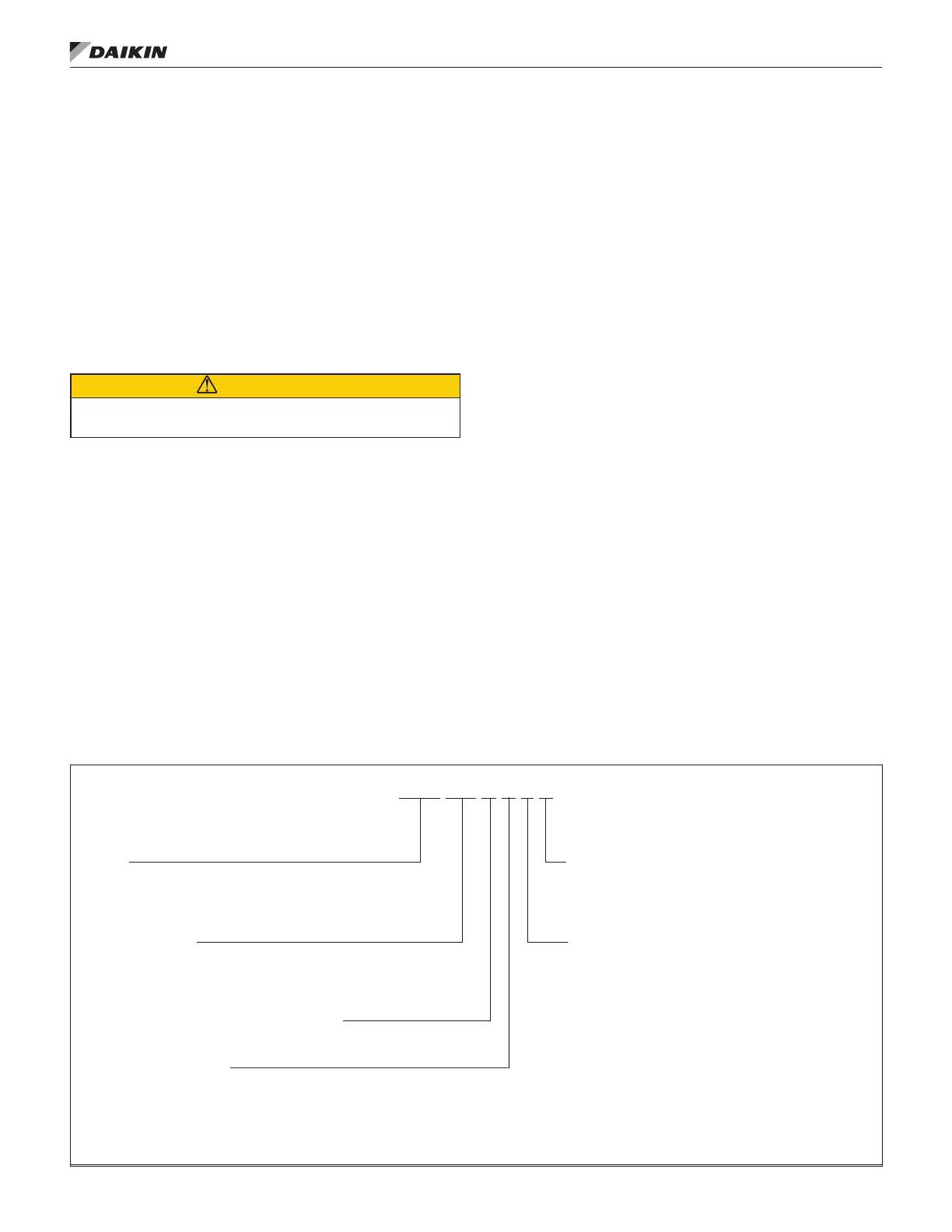
CAH 169 G D A C
Model
CAH = Custom modular air handler
CAC = Custom modular component
(cataloged size—nominal square foot of coil)
107, 124, 141, 160, 169
Vintage of Daikin Applied air handling unit
B = Blow-through cooling coil location
D = Draw-through cooling coil location
H = Heating only
V = Vent only
M = Multizone
C = Standard unit cross section
M = Custom size cross section
Motor location
A = Motor along side of fan housing
C = Motor downstream of ECM fan
D = Motor downstream of belt-drive plenum fan
G = Motor downstream of direct-drive plenum fan
H = Motor downstream of direct-drive plenum fan
in fan array
T = Motor behind twin fan housing
 Loading...