IM 915-13 • VISION - EXTENDED SIZES 32 www.DaikinApplied.com
The Daikin Applied EC Fan Array is made of an impeller, EC
motor, and inverter. It is installed as an assembly, and in the
event of failure, the entire assembly must be replaced. Bearings
are permanently sealed and lubricated, so no periodic greasing
is necessary.
A minimum 24” access section is recommended downstream
of the ECM fan array section to gain access to the fans.
If an access section is not selected downstream of the
fan array, there will be very limited access to the fans for
service/replacement.
There are three control oerings; none, manual/auto,
and digital controls. For manual/auto, an HOA switch and
potentiometer are included. For none and manual/auto, the
entire array is controlled via a 0-10V signal. Control signal
is wired to points 3 and 4 on the Daikin Applied low voltage
terminal strip seen in Figure 50. There are two other points for
the EC Fan Array: fan array enable and disable are points 1
and 2, and fan array fault are points 5 and 6. If any fan in the
fan array faults, the contact connection between 5 and 6 will
open.
To DISABLE the array, connect points 1 and 2
together. The array defaults to ENABLE with
nothing connected to points 1 and 2.
The digital controls option is a DDC controller allowing for
equipment conguration, monitoring, and troubleshooting.
The controller is either factory installed on the unit or remote
mounted. Reference OM 1329 for conguration and operation
information. The Daikin Applied EC Fan Array has an optional
gravity actuated block o damper. These dampers are
equipped with counter weights.
The EC Fan Array has an option for a block o plate that can
be ordered as a parts kit from the Daikin Applied Parts group. A
minimum 24” access section is recommended upstream of the
ECM fan array section to install block-o plate.
Remote Mounted Panel
The control panel can be ordered for remote mounting. For
remote mounted panels, the control wiring for the individual
fans will be provided; however, the control wiring to connect the
nal fan to the control panel and all of the power wiring must
be eld-provided. If control panel is too heavy to be mounted
on unit then it will be shipped separately and must be remote
mounted.
30 foot long high voltage harnesses may be ordered through
the Daikin Applied Parts Group using part number 910232406.
One high voltage harness is required per fan.
If wiring harnesses are not purchased through Daikin Applied,
follow the below instructions to install the wiring.
1. High Voltage Power Wiring:
a. Remove the plate on the back of each fan.
b. Remove the provided high voltage plug and wiring
shown in Figure 49.
c. Cut, strip, and connect wiring directly to each
motor terminal shown in Figure 49, paying
attention to the correct phasing. Reference the
wiring shematic provided with unit. Wiring to be in
accordance with NEC.
d. Cut, strip, and connect the other end of the wiring
to the Manual Motor Protector (MMP) in the control
panel, paying attention to phasing. Reference the
wiring shematic provided with unit.
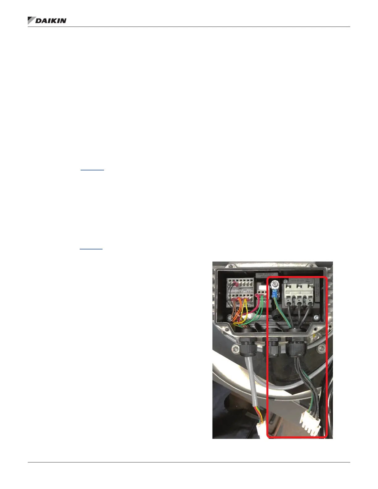
Figure 50 shows a single fan control box. There will
be 1 MMP per fan in the array to connect each fan to.
2. Low Voltage Control Wiring:
a. Verify same plugs and terminals are used for all
control options and fan types.
b. 22-gauge Cat5 wiring, a standard 6-circuit female
Molex plug (39-01-2061), and six Molex crimp
terminals (39-00-0040) are required (Figure 51).
The nished harness will have a plug on one end
and stripped wire on the other end.
c. Attach the wiring to the Molex crimp terminal
and insert into the Molex plug. See Figure 52
for correct crimp terminal locations; reference
schematic shipped with unit for wiring numbers
(out of ECM01). Connect to the male plug that is
on the last fan in the array.
d. Insert the stripped wire end into the terminals in the
control panel, following the wiring diagram shipped
with unit. Terminals are shown in Figure 50.
Figure 49: Fan - High Voltage Wiring
 Loading...