26 | Technical data
Installer and user reference guide
167
REYQ8~20+REMQ5U7Y1B
VRV IV+ heat recovery
4P561154-1A – 2020.10
3 For connection wiring to indoor–outdoor transmission F1‑F2,
outdoor‑outdoor transmission F1‑F2, outdoor‑multi transmission Q1‑Q2,
refer to the installation manual.
4 How to use BS1~BS3 switch, refer to the "Service Precaution" label on the
electrical component box cover.
5 When operating, do NOT short-circuit the protection devices (S1PH, S2PH
(for 14~20 HP only)).
6 For 5~12 HP: When using the optional accessory, refer to the installation
manual of the optional accessory.
6 For 14~20 HP: connector X1A (M2F is red, connector X2A (M2F) is white.
7 For 5~12 HP: Colours (see below).
7 For 14~20 HP: When using the optional accessory, refer to the installation
manual of the optional accessory.
8 For 14~20 HP: Colours (see below).
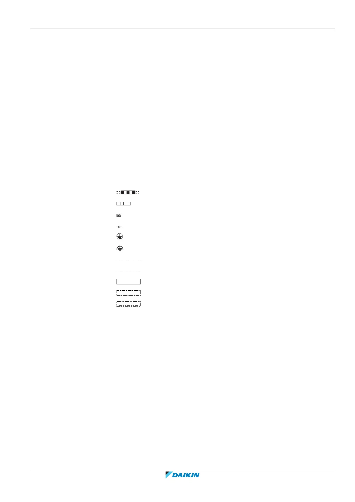
Symbols:
Field wiring
Terminal block
Connector
Terminal
Protective earth
Noiseless earth
Earth wiring
Field supply
PCB
Switch box
Option
Colours:
BLK Black
RED Red
BLU Blue
WHT White
GRN Green
Legend for wiring diagram 5~12 HP:
A1P Printed circuit board (main)
A2P Printed circuit board (noise filter)
A3P Printed circuit board (inverter)
A4P Printed circuit board (fan)
A5P Printed circuit board (sub)
BS1~BS3 (A1P) Push button switch (MODE, SET, RETURN)

 Loading...