18 | Piping installation
Installer and user reference guide
94
REYQ8~20+REMQ5U7Y1B
VRV IV+ heat recovery
4P561154-1A – 2020.10
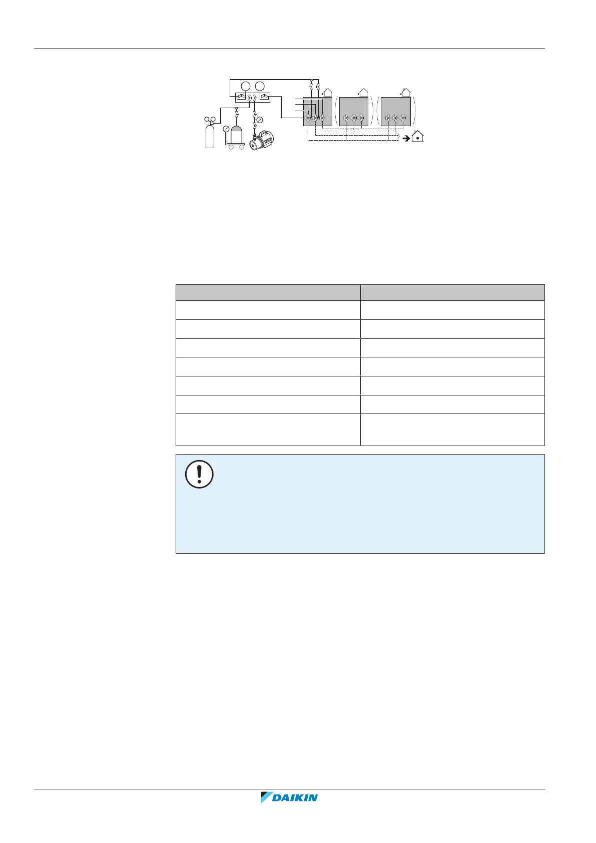
18.3.3 Checking refrigerant piping: Setup
a Pressure reducing valve
b Nitrogen
c Weighing scales
d Refrigerant R410A tank (siphon system)
e Vacuum pump
f Liquid line stop valve
g Gas line stop valve
h High pressure/low pressure gas line stop valve
A Valve A
B Valve B
C Valve C
D Valve D
Valve State of valve
Valve A Open
Valve B Open
Valve C Open
Valve D Open
Liquid line stop valve Close
Gas line stop valve Close
High pressure/low pressure gas line
stop valve
Close
NOTICE
The connections to the indoor units and all indoor units should also be leak and
vacuum tested. Keep any possible (field supplied) field piping valves open as well.
Refer to the indoor unit installation manual for more details. Leak test and vacuum
drying should be done before the power supply is set to the unit. If not, see also the
flow chart earlier described in this chapter (see "About checking the refrigerant
piping"[492]).
18.3.4 To perform a leak test
The leak test must satisfy the specifications of EN378‑2.
To check for leaks: Vacuum leak test
1 Evacuate the system from the liquid and gas piping to –100.7kPa (–1.007bar)
(5Torr absolute) for more than 2 hours.
2 Once reached, turn off the vacuum pump and check that the pressure does
not rise for at least 1 minute.
3 Should the pressure rise, the system may either contain moisture (see vacuum
drying below) or have leaks.
To check for leaks: Pressure leak test
1 Test for leaks by applying a bubble test solution to all piping connections.
2 Discharge all nitrogen gas.
 Loading...