26 | Technical data
Installer and user reference guide
166
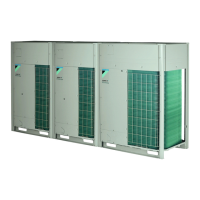
REYQ8~20+REMQ5U7Y1B
VRV IV+ heat recovery
4P561154-1A – 2020.10
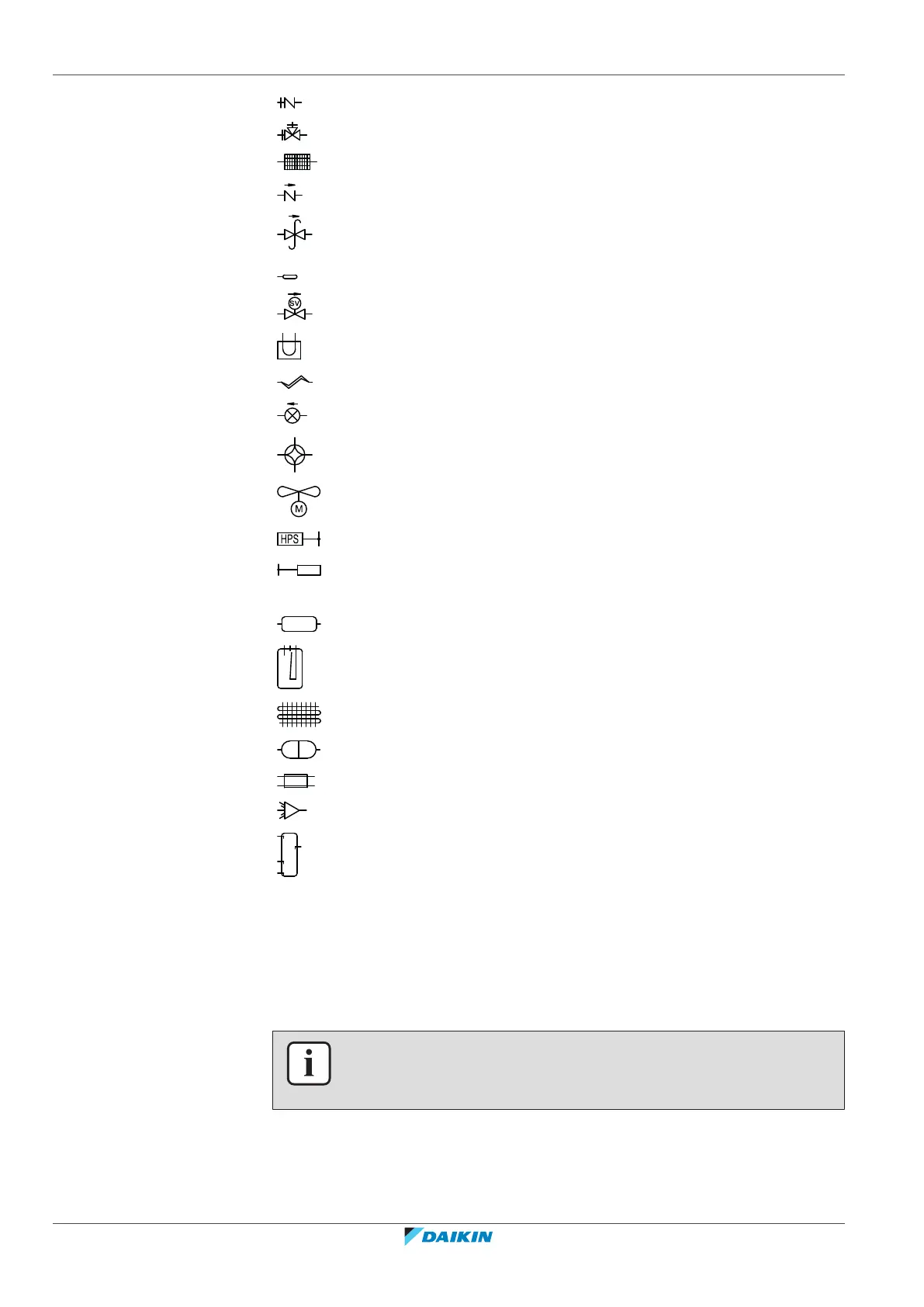
Charge port / Service port
Stop valve
Filter
Check valve
Pressure relief valve
Thermistor
Solenoid valve
Heat sink (PCB)
Capillary tube
Expansion valve
4‑way valve
Propeller fan
High pressure switch
Low pressure sensor
High pressure sensor
Oil separator
Accumulator
Heat exchanger
Compressor
Double tube heat exchanger
Distributor
Liquid receiver
26.3 Wiring diagram: Outdoor unit
Refer to the wiring diagram sticker on the unit. The abbreviations used are listed
below:
INFORMATION
The wiring diagram on the outdoor unit is only for the outdoor unit. For the indoor
unit or optional electrical components, refer to the wiring diagram of the indoor unit.
1 This wiring diagram applies only to the outdoor unit.
2 Symbols (see below).
 Loading...