23 | Maintenance and service
Installer and user reference guide
152
REYQ8~20+REMQ5U7Y1B
VRV IV+ heat recovery
4P561154-1A – 2020.10
BLK
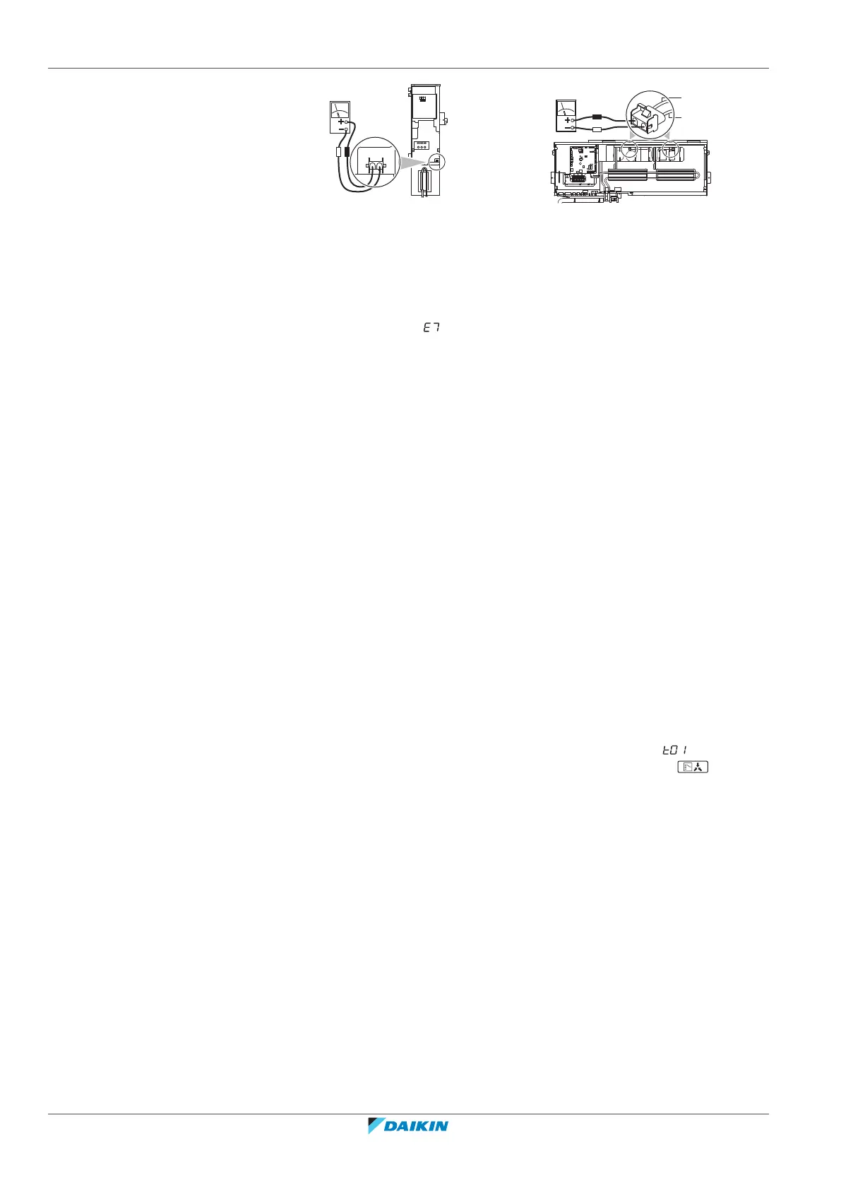
RED
X6A (A6P) X5A (A3P)
14~20 HP
3 Pull out junction connectors X1A, X2A for the fan motors in the outdoor unit
before starting service operation on the inverter equipment. Be careful not to
touch the live parts. (If a fan rotates due to strong wind, it may store
electricity in the capacitor or in the main circuit and cause electric shock.)
4 After the service is finished, plug the junction connector back in. Otherwise
the malfunction code will be displayed on the user interface or on the
outdoor unit 7‑segment display and normal operation will not be performed.
For details refer to the wiring diagram labelled on the back of the electrical
component box cover.
Pay attention to the fan. It is dangerous to inspect the unit while the fan is running.
Make sure to turn off the main switch and to remove the fuses from the control
circuit located in the outdoor unit.
23.2 About service mode operation
Refrigerant recovery operation/vacuuming operation is possible by applying setting
[2‑21]. Refer to "20.2Making field settings"[4122] for details how to set mode2.
When vacuuming/recovery mode is used, check very carefully what should be
vacuumed/recovered before starting. See installation manual of the indoor unit for
more information about vacuuming and recovery.
23.2.1 To use vacuum mode
1 When the unit is at standstill, set the unit in [2‑21]=1.
Result: When confirmed, the indoor and outdoor unit expansion valves will
fully open. At that moment the 7‑segment display indication= and the user
interface of all indoor units indicate TEST (test operation) and (external
control) and the operation will be prohibited.
2 Evacuate the system with a vacuum pump.
3 Press BS3 to stop vacuuming mode.
23.2.2 To recover refrigerant
This should be done with a refrigerant recovery unit. Follow the same procedure as
for vacuuming method.
 Loading...