18 | Piping installation
Installer and user reference guide
72
REYQ8~20+REMQ5U7Y1B
VRV IV+ heat recovery
4P561154-1A – 2020.10
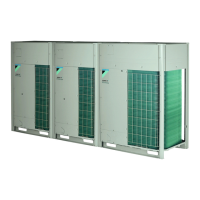
A, B, C: Piping between outdoor unit and (first) refrigerant branch kit
Choose from the following table in accordance with the outdoor unit total capacity
type, connected downstream.
Outdoor unit capacity
type (HP)
Piping outer diameter size (mm)
Liquid pipe Suction gas pipe High pressure/
low pressure gas
pipe
5~8 9.5 19.1 15.9
10 9.5 22.2 19.1
12 12.7 28.6 19.1
14~16 12.7 28.6 22.2
18 15.9 28.6 22.2
20~22 15.9 28.6 28.6
24 15.9 34.9 28.6
26~34 19.1 34.9 28.6
36 19.1 41.3 28.6
38~54 19.1 41.3 34.9
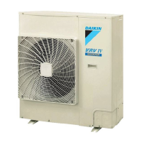
D: Piping between refrigerant branch kits or refrigerant branch kit and BS unit
Choose from the following table in accordance with the indoor unit total capacity
type, connected downstream. Do not let the connection piping exceed the
refrigerant piping size chosen by the general system model name.
Indoor unit capacity index Piping outer diameter size (mm)
Liquid pipe Suction gas pipe High pressure/
low pressure gas
pipe
<150 9.5 15.9 12.7
150≤x<200 19.1 15.9
200≤x<290 22.2 19.1
290≤x<420 12.7 28.6
420≤x<640 15.9 28.6
640≤x<920 19.1 34.9
≥920 41.3
Example:
▪ Downstream capacity for E=[capacity index of unit 1]
▪ Downstream capacity for D=[capacity index of unit 1]+[capacity index of unit 2]
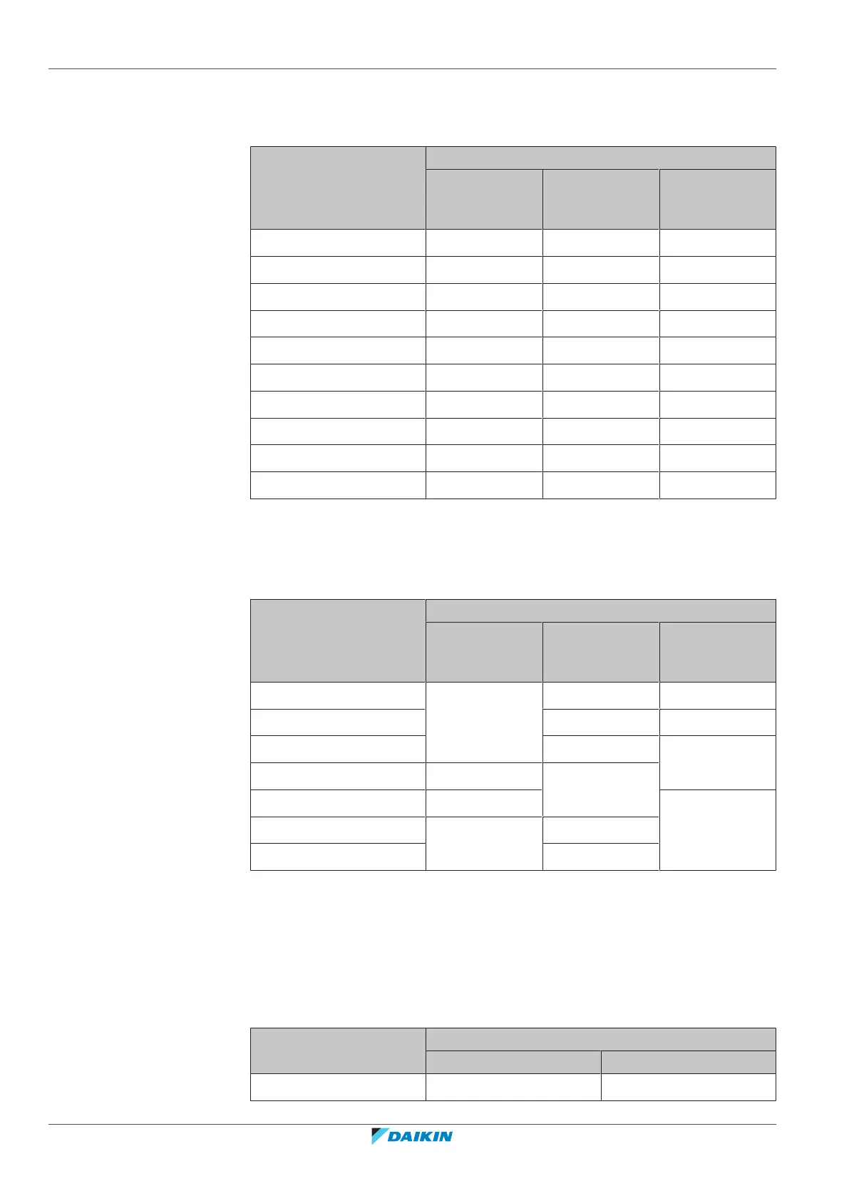
E: Piping between refrigerant branch kit or BS unit and indoor unit
Pipe size for direct connection to indoor unit must be the same as the connection
size of the indoor unit (in case indoor unit is VRVDX indoor or Hydrobox).
Indoor unit capacity index Piping outer diameter size (mm)
Gas pipe Liquid pipe
15~50 12.7 6.4

 Loading...