Daktronics scoreboards use
1/2" and 5/8" shoulder-type eyebolts mounted to a 1/8"
aluminum plate or steel nut plate, but exceeding load angles or weight limits could
cause the bolts to pull out or the scoreboard cabinet to buckle. In either circumstance,
there could be serious damage to the scoreboard. If you must use this method, ensure
a minimum angle between the chain and scoreboard of at least 45degrees.
Note: Daktronics assumes no liability for scoreboard damage resulting from
incorrect setup or incorrect lifting methods. Eyebolts are intended for lifting only. Do
not attempt to permanently support the display with the eyebolts.
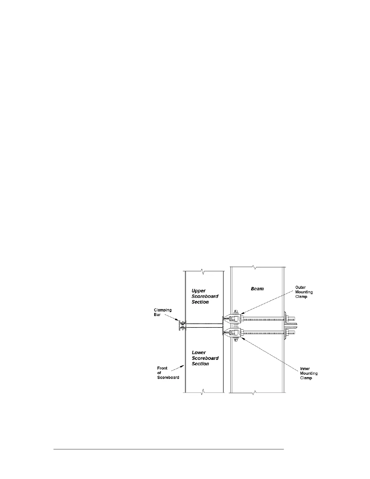
In typical multi-section installations, the lower scoreboard is installed first and
secured to the support beams. The upper section is then placed atop or above the
lower section and attached to the beams. There may be cables extending from the top
of the lower section. Guide these cables into the hole in the bottom of the upper
section for later connection.
If installers remove the lift eyebolts, plug the holes with bolts and the rubber sealing
washers used with the eyebolts. Apply silicone or another waterproof sealant to the
eyebolt openings. Inspect the top and sides of the display for any other holes or
openings that may allow moisture to enter the display, and plug and seal those
openings as well.
6.4 Scoreboard Mounting
Reference Drawings:
Display Mounting ............................................................ Drawing A-44412
Display Mounting Straps, BA-3718 .............................. Drawing A-114415
Scoreboards can be mounted
on two, three, or four poles.
Refer to Section 6.2 to
determine the center-to-
center distance of the poles
and other installation
specifications for each
model.
Figure 4: Multi-Section Scoreboard Mounting (Side View)
Drawing A-44412 shows
the hardware used for
mounting the scoreboard to
the beams. Each section of
the scoreboard attaches at
the top and the bottom to all
the beams. The drawing also
shows top and side views of
the scoreboard secured to the
beams. Note that the
threaded rods do not pass
through the flanges of the
beams, but instead run along
both sides of each beam.
Mechanical Installation 6-5
 Loading...

