Replacing a
Driver
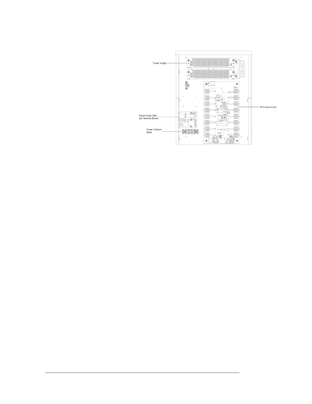
Figure 14: 16-Column Driver Enclosure
Drivers are typically mounted
inside the scoreboard and
immediately behind a digit, but
location and mounting varies
with the model of the
scoreboard. Refer to the
component locations drawings
in Section 4 for the location of
your scoreboard driver.
All scoreboards in this manual
are front-accessible. Each
driver is enclosed with a power
supply and signal terminal
block.
Before a failed driver can be
reached, the enclosure must be
accessed. Follow these steps:
1. Open the digit panel or scoreboard face panel as described in Section 8.2.
2. Remove the cover from the driver enclosure.
3. Disconnect all connectors from the driver. Release each connector by
squeezing together the locking tabs as you pull the connector free.
Note: This is a keyed connector and will attach in one way only. Do not
attempt to force the connections!
4. Remove the screws, nuts, or wing nuts securing the driver to the inside of
the enclosure. Refer to Figure 14.
5. Carefully lift the driver from the display and place it on a clean, flat surface.
6. Follow steps 1 through 5 in reverse order to attach a new driver.
8.3 Schematic
Reference Drawings:
Schematic; Gen III & IV, OD LED, 3 Drvr Display .............. Drawing A-179541
Schematic; Gen III & IV, OD LED, 1 Drv w/TNMC ............. Drawing A-179790
Schematic; Gen III & IV, OD LED, 3Drv w/TNMC .............. Drawing A-180081
Schematic; Gen III & IV, OD LED, 2 Drv ............................ Drawing A-180637
Schematic; Gen III & IV, OD LED,
2 Drv Multi-Sec w/TNMC .......................................... Drawing A-180688
Schematic; Gen IV Outdoor LED, 16 Column Drvr ............ Drawing A-285779
Drawings A-179541, A-179790, A-180081, A-180637, A-180688 and A-285779 are
the schematic diagrams for the Daktronics multi-section scoreboards and the 16-
column drivers used in them. The schematics include power and signal inputs and all
8-4 Scoreboard Maintenance
and Trouble Shooting
 Loading...

