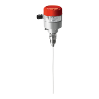
3.4 Dimensions and
appearance
3.5 Cable gland opening
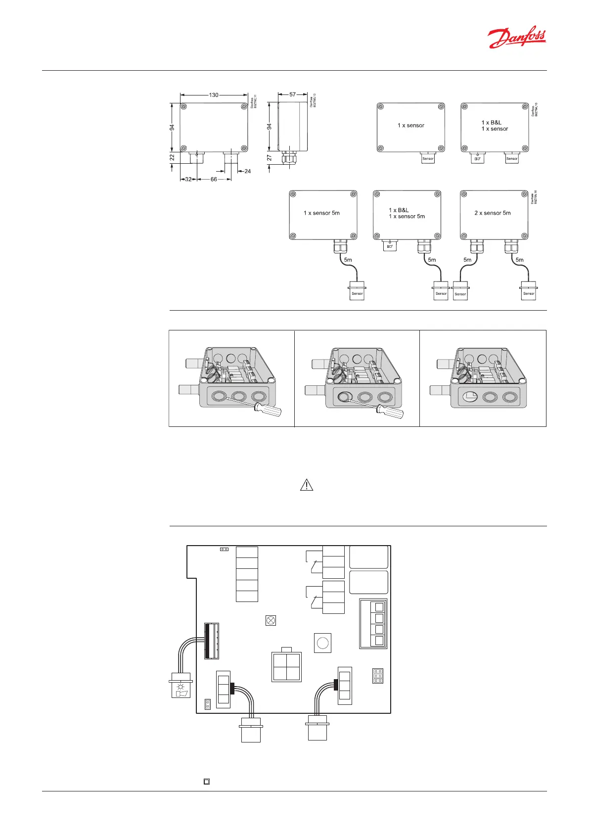
3.6 Board pinout
148H126_01-2018
Hole punching for cable gland:
1. Select the location for the safest
cable entry
2. Use a sharp screwdriver and a
small hammer
3. Place the screwdriver and
hammer with precision while
moving the screwdriver within
a small area until the plastic is
penetrated.
Continue precision punching with
small movements until the round
piece can be pulled out with your
fingers.
WARNING: be very careful not to damage the internal
board components with the screwdriver.
Remove potential burrs and secure
flat surfaces.
Install the cable gland according to
the enclosed guide.
JP5
5
4
2
1
not used
GND
AO_01
DI_01
S&H supply
x1
open: 0-20mA
closed: 0-10V
LED
Yellow/Green/Red
1
2
3
1
2
3
x6
x5
Rel. 3
Rel. 1
x4
4
3
2
1
not used
JP3
JP2
JP1
x3
Ackn.-/Test
button
Sensor 1
Sensor 2
Tool
x9
x2
x8
B&L
JP4
Danfoss
80Z790.1
open: 19200 Baud
closed: 38400 Baud
B-
MODBUS
A+
-
24 V AC/D
+
(critical)
(warning)
Note: For what concern the power supply, please refer to chapter 3.10 Power Conditions and Shielding
Conceptions.
A Class II power supply is recommended
Fig. 1
Fig. 2
Fig. 3
User Guide | Danfoss Gas sensor, type DGS
4 | BC291049702513en-000201 © Danfoss | Climate Solutions | 2022.01

 Loading...