3.9 Troubleshooting
3.10 Power Conditions and
Shielding Conceptions
Symptom: Possible cause(s):
LED off • Check power supply. Check wiring.
• DGS MODBUS was possibly damaged in transit. Check by installing another DGS
to confirm the fault.
Green flashing • The sensor calibration interval has been exceeded or the sensor has reached the
end of life. Carry out calibration routine or replace with a new factory calibrated
sensor.
Yellow • AO configured but not connected (only 0 – 20 mA output). Check wiring.
• Sensor type does not match DGS specification. Check gas type and measuring
range.
• Sensor may be disconnected from printed circuit board. Check to see if the sensor
is properly connected.
• The sensor has been damaged and needs to be exchanged. Order replacement
sensor from Danfoss.
• Supply voltage out of range. Check power supply.
Yellow flashing • The DGS is set to service mode from the hand-held Service Tool. Change setting
or await time-out within 15 minutes.
Alarms in the absence
of a leak
• If you experience alarms in the absence of a leak, try setting an alarm delay.
• Perform a bump test to ensure proper operation.
The zero-measurement
drifts
The DGS-SC sensor technology is sensitive to the environment (temperature, moist,
cleaning agents, gases from trucks, etc). All ppm measurements below 75 ppm
should be disregarded, i.e. no zero-adjustment made.
Standalone DGS without Modbus network communication
Shield/screen is not required for standalone DGS with no connection to a RS-485 communication line.
However, it can be done as described in the next paragraph (Fig. 4).
DGS with Modbus network communication in combination with other devices powered by the
same power supply
It is strongly recommended to use direct current power supply when:
• more than 5 DGS units are powered by the same power supply
• the bus cable length is longer than 50 m for those powered units
It is moreover recommended to use class 2 power supply (see AK-PS 075)
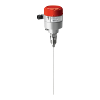
Make sure to not interrupt the shield when connecting A and B to the DGS (see Fig. 4).
Fig. 4: Loop trough
A
+
B
–
Danf
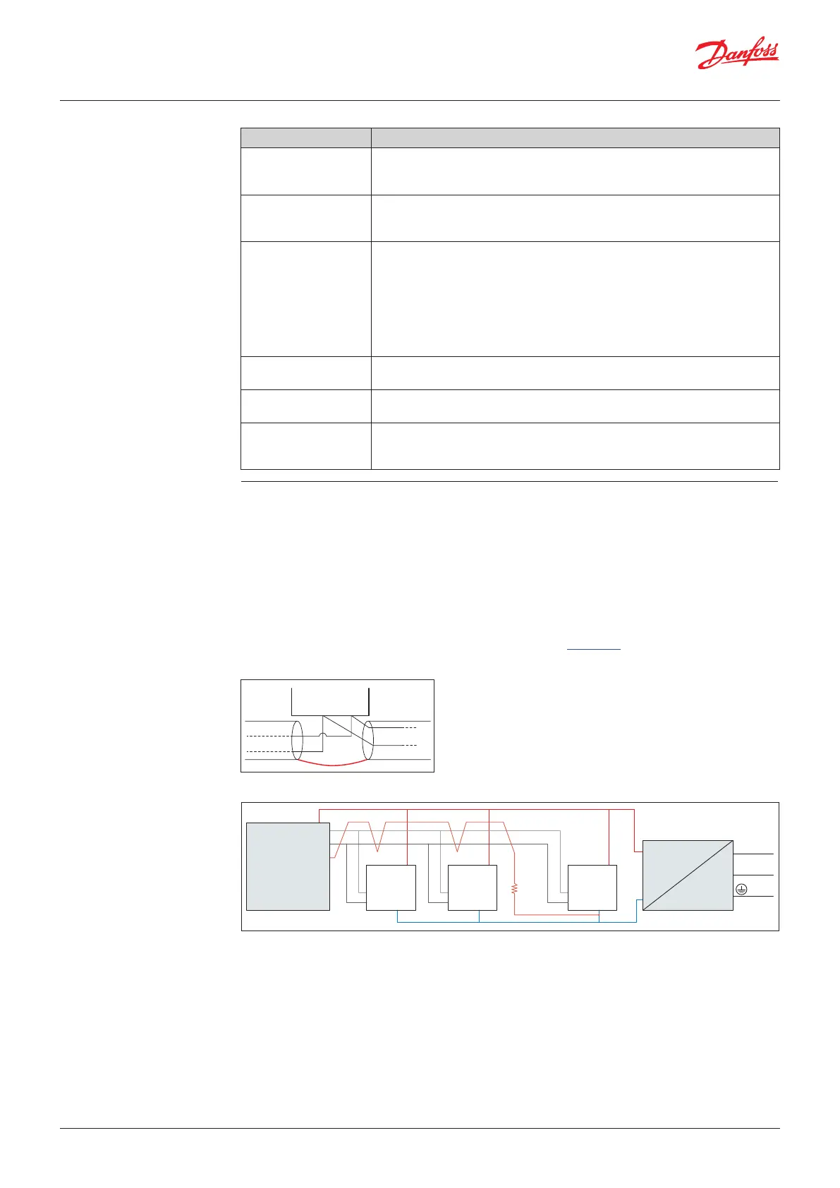
Ground potential difference between nodes of the RS485 network might affect the communication.
It is advised to connect a 1 KΩ 5% ¼ W resistor between the shield and the ground (X4.2) of any unit
or group of units connected to the same power supply (Fig. 5).
Please refer to Literature No. AP363940176099.
Fig. 5: Wiring diagram for system with one power supply
Danfoss
80Z876
L
N
230 V
DGS 1
#adr 10
Shield
+
A
B Gnd
DGS 2
#adr 11
+
A
B Gnd
DGS n
#adr xx
1 KΩ
+
A
B Gnd
AK-PS 075 power supply
A
B
Shld
Danfoss
Modbus
device
+
–
Input 230 V
User Guide | Danfoss Gas sensor, type DGS
© Danfoss | Climate Solutions | 2022.01 BC291049702513en-000201 | 7

 Loading...