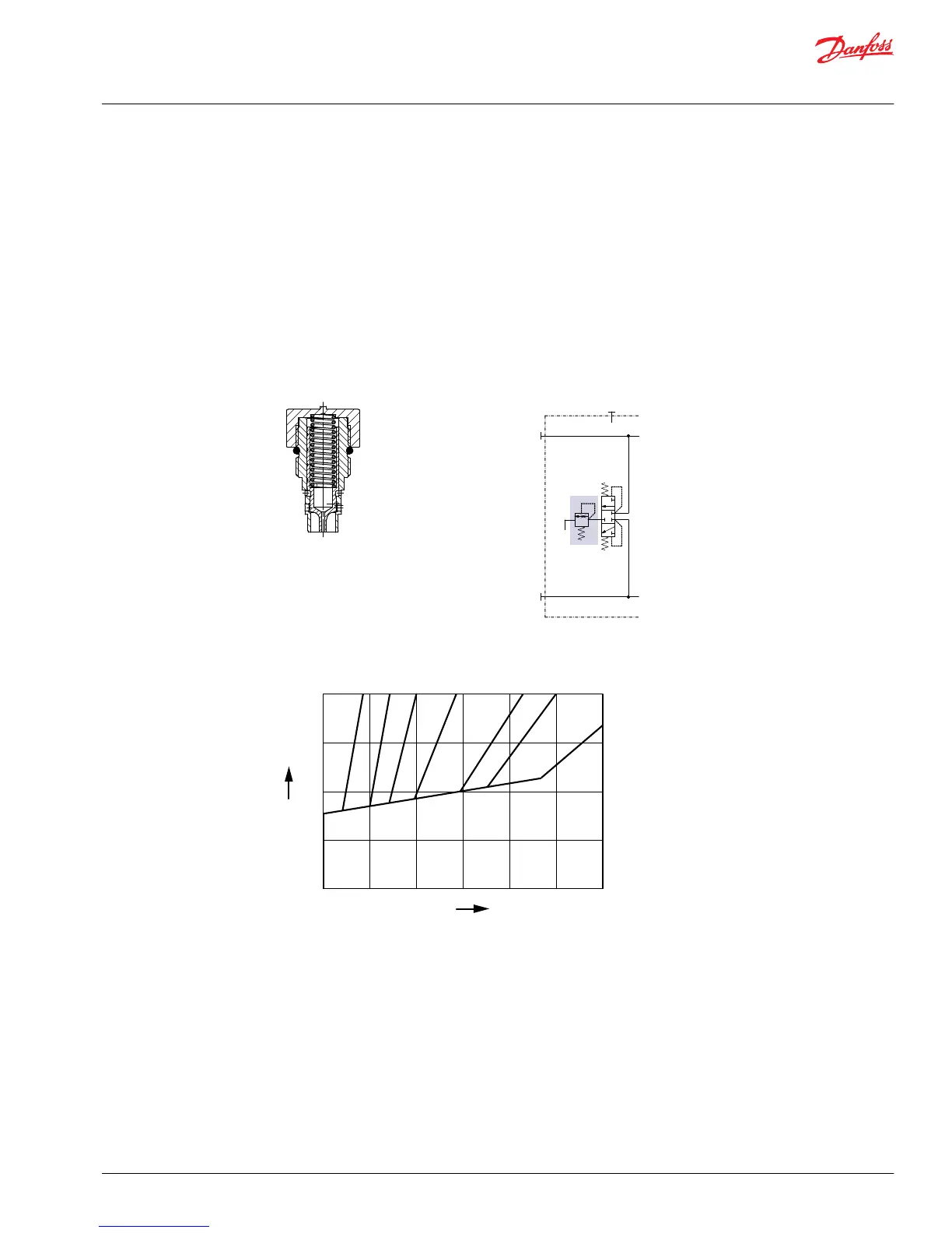
Loop flushing relief valve
The loop flushing relief valve is incorporated into all H1 motors and uses the loop flushing option in
installations that require fluid to be removed from the low pressure side of the system circuit due to
cooling requirements.
The loop flushing relief valve is also used to facilitate the removal of contaminants from the loop.
The loop flushing valve is equipped with an orificed charge pressure relief valve designed with a cracking
pressure of 16 bar [232 psi].
Valves are available with several orifice sizes to meet the flushing flow requirements of all system
operating conditions.
Loop flushing relief valve (cross section)
X Loop flushing flow (l/min)
Y Low system pressure minus case pressure (bar)
Service Manual
H1 Bent Axis Motors, Size 060/080/110/160/210/250 cm3
Operation
©
Danfoss | August 2018 AX00000025en-US0504 | 21
 Loading...