Warning
Error pins from more PVEs may not be interconnected. Not activated error pins are connected to ground
and will disable any active signal. Error pins are signal pins and can only supply very limited power
consumption.
To avoid the electronics in undefined state a general supervision of power supply (U
DC
) and internal clock
frequency is implemented. This function applies to PVEA, PVEH, PVEP, PVES and PVEU independently of
fault monitoring version and PVEM - and will not activate fault monitoring.
The solenoid valves are disabled when:
•
the supply voltage exceeds 36 V
•
the supply voltage falls below 8.5 V
•
the internal clock frequency fails
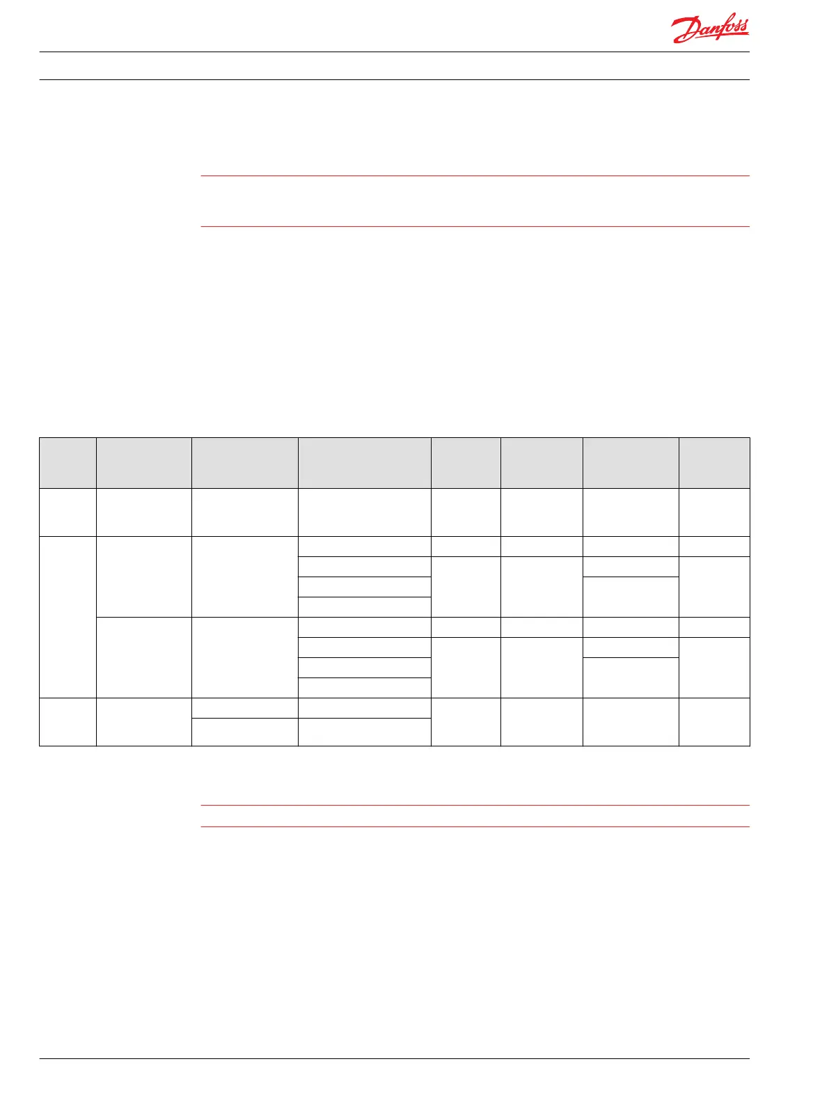
PVE fault monitoring overview
PVE type Fault monitoring Delay before error
out
Error mode Error output
status
Fault output
on PVE
1)
LED light Memory
(reset
needed)
PVEO
PVEM
PVHC
No fault
monitoring
- - - - - -
PVEA
PVEH
PVEP
PVES
PVEU
Active 500 ms
(PVEA: 750 ms)
No fault Low < 2 V Green -
Input signal faults High ∼U
DC
Flashing red Yes
Transducer (LVDT) Constant red
Close loop fault
Passive 250 ms
(PVEA: 750 ms)
No fault Low < 2 V Green -
Input signal faults High ~U
DC
Flashing red No
Transducer (LVDT) Constant red
Close loop fault
PVE
Float
six pin
Active 500 ms Float not active High ~U
DC
Constant red Yes
750 ms Float still active
1)
Measured between fault output pin and ground.
Warning
It’s up to the customer to decide on the required degree of safety for the system.
For PVE with direction indication:
•
both DI pins go low when error is active.
•
when U
DC1
is disabled, U
S
is not monitored and defined as 50%.
Spool position feedback (-SP)
The –SP functionality is a 0,5 V to 4,5 V feedback, inverted in direction relative to U
S
with 2,5 V as neutral
value.
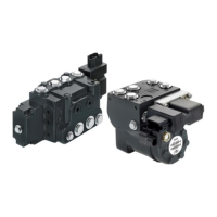
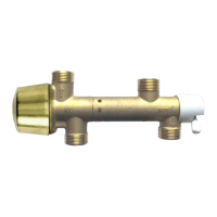
Technical Information
PVE, Series 4 for PVG 32/100/120 and PVHC
Safety and monitoring
16 520L0553 • Rev GD • Jan 2014

 Loading...