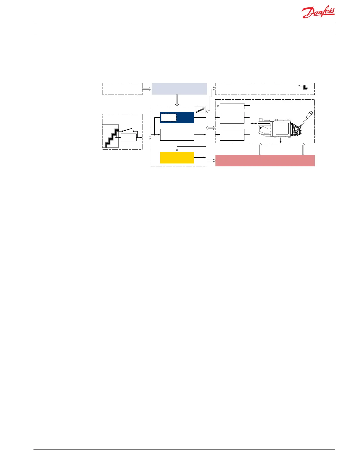
Electrical block diagram for above illustration
Supply
Control
Neutral
Detection
Signal
Conditioning
Failure
Detection
Fault
Monitoring
PVE fault output
Signal
Conditioning
Supply
Main controller
Hydraulic deactivation
HMI / Joystick
Control
Signal
Emergency stop and
Man present switch
Motion detection sensor
PVE
Main control valve
Main power supply
(battery)
Joystick
neutral switch
P301 317
Typical wiring block diagram example
Example of a typical wiring block diagram using PVEH with neutral power off switch and fault monitoring
output for hydraulic deactivation.
Technical Information PVE, Series 4 for PVG 32/100/120 and PVHC
Safety in application
520L0553 • Rev GD • Jan 2014 21

 Loading...