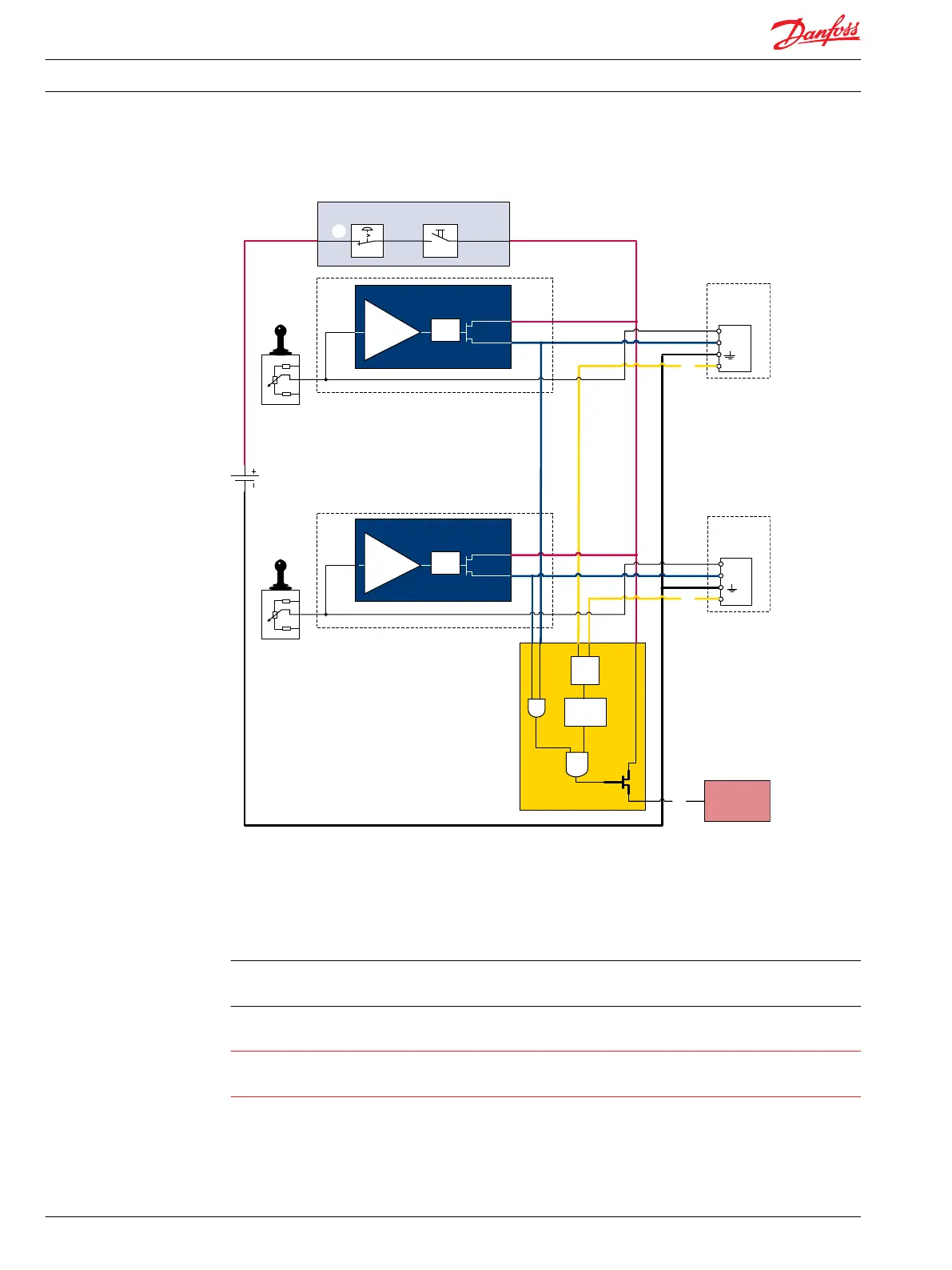
Typical wiring block diagram example
Fault detection output
high=on
low=off
Alarm
logic
2)
Memory3)
E1
E2
Output
AND
OR
U
DC2
Error
U
S
Neutral detection / Supply control
signal
≠
neutral
OFF
Delay
1)
U
DC2
Error
U
S
PVEH
with AMP
connector
PVEH
with AMP
connector
Hydraulic
deactivation
Neutral detection / Supply control
signal
≠
neutral
OFF
Delay
1)
PVE 1
PVE 2
Emergency
stop
Man present
switch
C
C
D
B
B
A
P301 318
A– Emergency stop / man present switch
B– PVE Faultmonitoring signals
C– Neutral signal detection.
D– Hydraulic deactivation
System Control Logic e.g. PLUS+1
®
for signal monitoring and triggering signal for deactivation of the
hydraulic system.
Warning
It is the responsebilty of the equipment manufacturer that the control system incorporated in the
machine is declared as being in confirmity with the relevant machine directives.
Technical Information
PVE, Series 4 for PVG 32/100/120 and PVHC
Safety in application
22 520L0553 • Rev GD • Jan 2014

 Loading...