EasyManuals Logo

Danfoss PVG 32 User Manual

Danfoss PVG 32
144 pages
To Next Page IconTo Next Page
To Previous Page IconTo Previous Page
Page #11 background image
PVG 16 installation
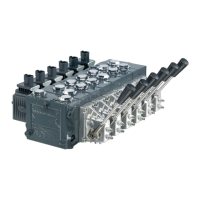
Standard assembled PVG 16
The exploded view illustration helps identify PVG 16 components to assist in installation.
Oil flow direction for standard assembled PVG 16
PVEO/A
PVHC
PVH
PVMD
PVP
PVS
PVB16
PVM
PVM
PVEA-F
PVEO/A-CI
C
xxxxxxxx
xxxxxxxx
xxxxxxxx
D
B
A
A
B
Identification
C: PVG number, week and year of installation and series number PVP- pressure setting
D: Engraved part number on PVP and PVB
Service and Parts Manual
PVG 16/32/128/256
Installation
©
Danfoss | October 2018 AX284661889190en-000101 | 11

Table of Contents

Other manuals for Danfoss PVG 32

Questions and Answers:

Question and Answer IconNeed help?

Do you have a question about the Danfoss PVG 32 and is the answer not in the manual?

Danfoss PVG 32 Specifications

General IconGeneral
CategoryControl Unit
Maximum working pressure350 bar
Size32
TypeProportional Valve
Maximum operating pressure420 bar
Porting patternISO 4401
Electrical connectionAMP

Related product manuals