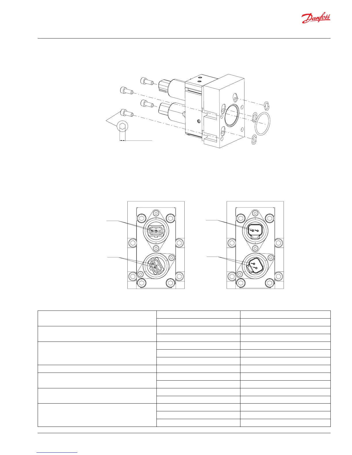
PVHC for PVG 128/256 connector
The seal in the PVHC connector and the seals for individual conductors are crucial for correctly sealing the
connector.
PVHC for PVG 128/256 technical data
Controller output current range 12 V 1 - 1500 mA
24 V 0 - 750 mA
Coil resistance 12 V 4.72 Ω ± 5%
24 V 20.8 Ω ± 5%
Pilot pressure (over tank)
*
Nominal 25 bar [363 psi]
Minimum 21 bar [305 psi]
Maximum 25 bar [363 psi]
Control pressure Range 5 - 15 bar [72.5 - 217.5 psi]
Max. tank pressure Port T Static 25 bar [363 psi]
Port T Dynamic 30 bar [435 psi]
Temperature range Ambient -30°C → 80°C [-22°F → 176°F]
Medium -20°C → 80°C [-4°F → 176°F]
Oil viscosity Operating range 12 → 75 mm2/s [65 → 347 SUS]
Minimum 4 mm
2
/s [39 SUS]
Maximum 400 mm
2
/s [2130 SUS]
Service and Parts Manual
PVG 16/32/128/256
Installation
©
Danfoss | October 2018 AX284661889190en-000101 | 49
 Loading...