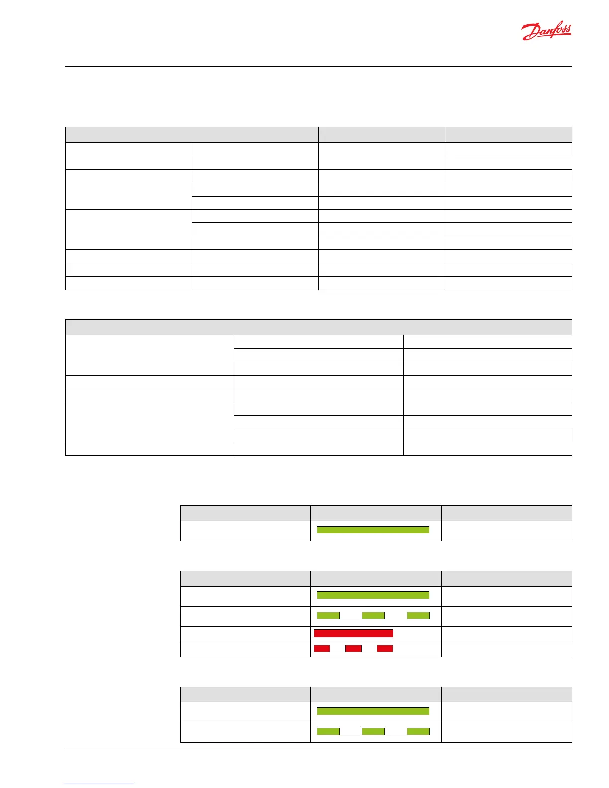
PVEH/H-FLA and PVEH-U control specifications
Control specification PVEH/H-FLA PVEH-U
Supply Voltage (Udc) Rated/Range 11→32 Vdc 11→32 Vdc
Max. ripple 5% 5%
Signal Voltage (Us) Neutral Us = 0.5 • Udc Us = 5 V
Q: P→A Us = (0.5→0.25) • Udc Us = 5 V→2.5 V
Q: P→B Us = (0.5→0.75) • Udc Us = 5 V→7.5 V
Signal Voltage PWM (Us) Neutral Us = 50% DUT
Q: P→A Us = 50%→25% DUT
Q: P→B Us = 50%→75% DUT
PWM Frequency (Us) Recommended >1000 Hz
Input Impedance Rated 12 kΩ
Input Capacitance Rated 100 nF
PVG 128/256 PVE operating conditions
PVEO, PVEH/H-U/H-FLA Operating Conditions
Pilot Pressure Nominal 13.5 bar [196 psi]
Minimum 10.0 bar [145 psi]
Maximum 15.0 bar [220 psi]
Storage Temperature Ambient -50°C→90°C [-58°F→194°F]
Operating Temperature Ambient -40°C→90°C [-40°F→194°F]
Oil Viscosity Operating range 12→75 cSt [65→347 SUS]
Minimum 4 cSt [39 SUS]
Maximum 460 cSt [2128 SUS]
Oil Cleanliness Maximum Maximum
PVG 128/256 PVE LED characteristics
PVEO LED characteristics
Color LED view Function
Green Power ON
PVEH/H-FLA LED characteristics
Color LED view Function
Green Operating
Green @ 1.5 Hz Neutral - Power Save
Red Internal fault
Red @ 1.5 Hz External or Float fault
PVEH-U LED characteristics
Color LED view Funtion
Green Operating
Green @ 1.5 Hz Neutral - Power Save
Service and Parts Manual
PVG 16/32/128/256
Installation
©
Danfoss | October 2018 AX284661889190en-000101 | 47
 Loading...